RJ45 Port Pinouts
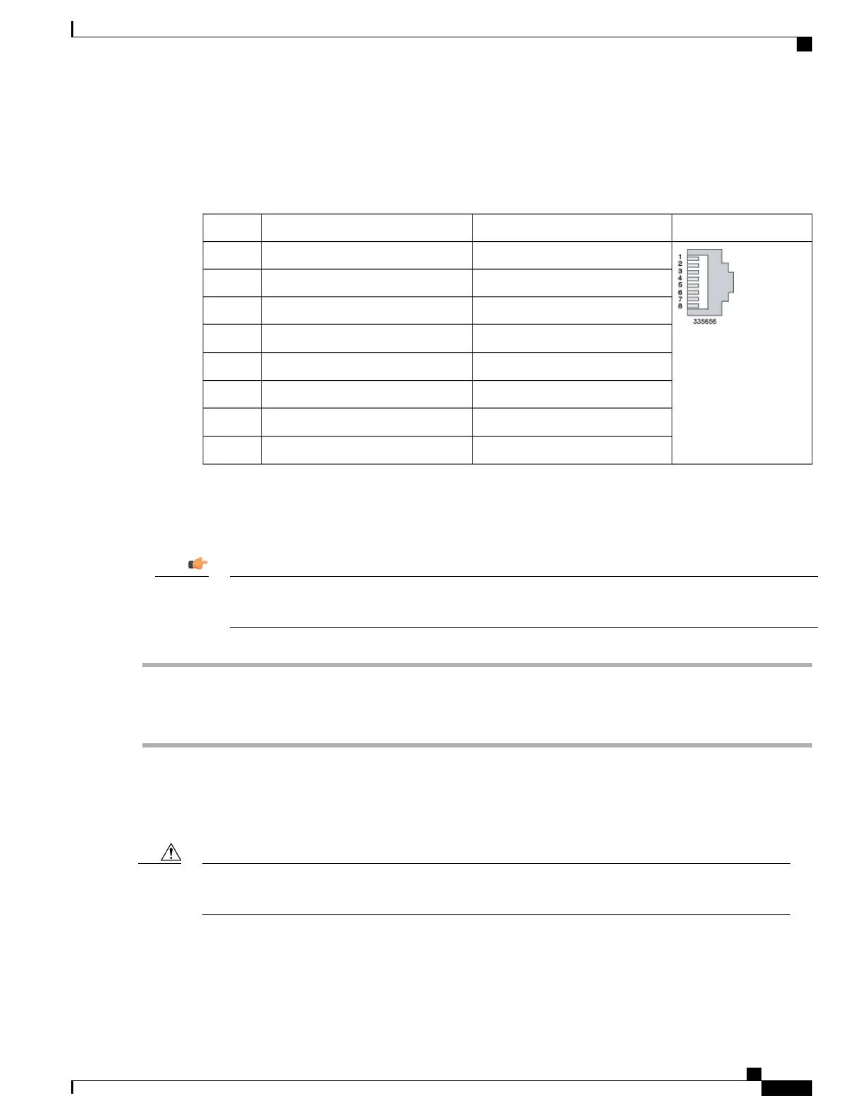
Table 12: 1000Base-T RJ45 Ethernet Pinouts
Pinout1000Base-T 1Gbps Cat5+100Base-T 100Mbps Cat5Pin
BI DA+TX+1
BI DA-TX-2
BI DB+RX+3
BI DC+
—
4
BI DC-
—
5
BI DB-RX-6
BI DD+
—
7
BI DD-
—
8
Connect 1000Base-T Interface to Network Device
To facilitate maintenance of the network cabling, the Cat-5 cables should be labeled with terminating
destinations.
Important
Step 1
Insert one end of the Cat-5 cable into the top MGMT connector (Port 1).
Step 2
Attach the other end of the Cat-5 cable to the appropriate network interface.
Step 3
Repeat Steps 1 and 2 to connect the bottom MGMT connector (Port 2).
10 GbE Optical Daughter Card Ports
The 10 Gigabit Ethernet ports on the daughter cards are only certified to work with SFP+ transceivers
tested and approved by Cisco. MIO and UMIO cards ship with SFP+ transceivers installed.
Caution
The 10 Gigabit Ethernet ports accept the following fiber optic to electrical signal Small Form-Factor Pluggable
(SFP+) transceiver types:
ASR 5500 Installation Guide
67
MIO Port Cabling
RJ45 Port Pinouts

 Loading...


