Never connect a high voltage/high current device such as an audible alarm/siren or incandescent lamp
directly to the EO alarm connector.
Caution
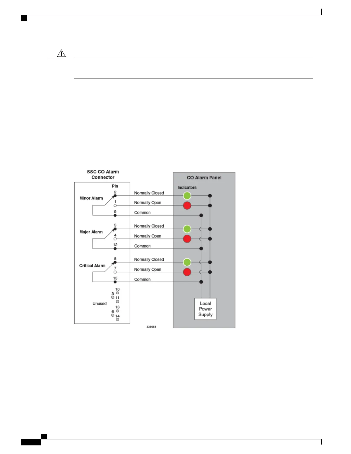
CO Alarm Wiring Example
The figure below depicts how the three dry-contact (no voltage supplied) relay contacts can each control up
to two alarming devices. In this example the SSC CO alarm interface is connected to a CO Alarm Panel, where
green LEDs are wired to indicate normal operation, and red LEDs are wired to indicate alarm conditions.
With all relays de-energized, the green LEDs are illuminated. If an alarm relay is energized, its NO (normally
open) contact closes; the green LED is extinguished and the red LED is illuminated.
Figure 20: CO Alarm Interface Schematic
ASR 5500 Installation Guide
76
SSC Alarm Cabling
CO Alarm Wiring Example

 Loading...


