CO alarm interface (DB15)2Connector cover plate1
Audible alarm4Alarm Cutoff (ACO) switch3
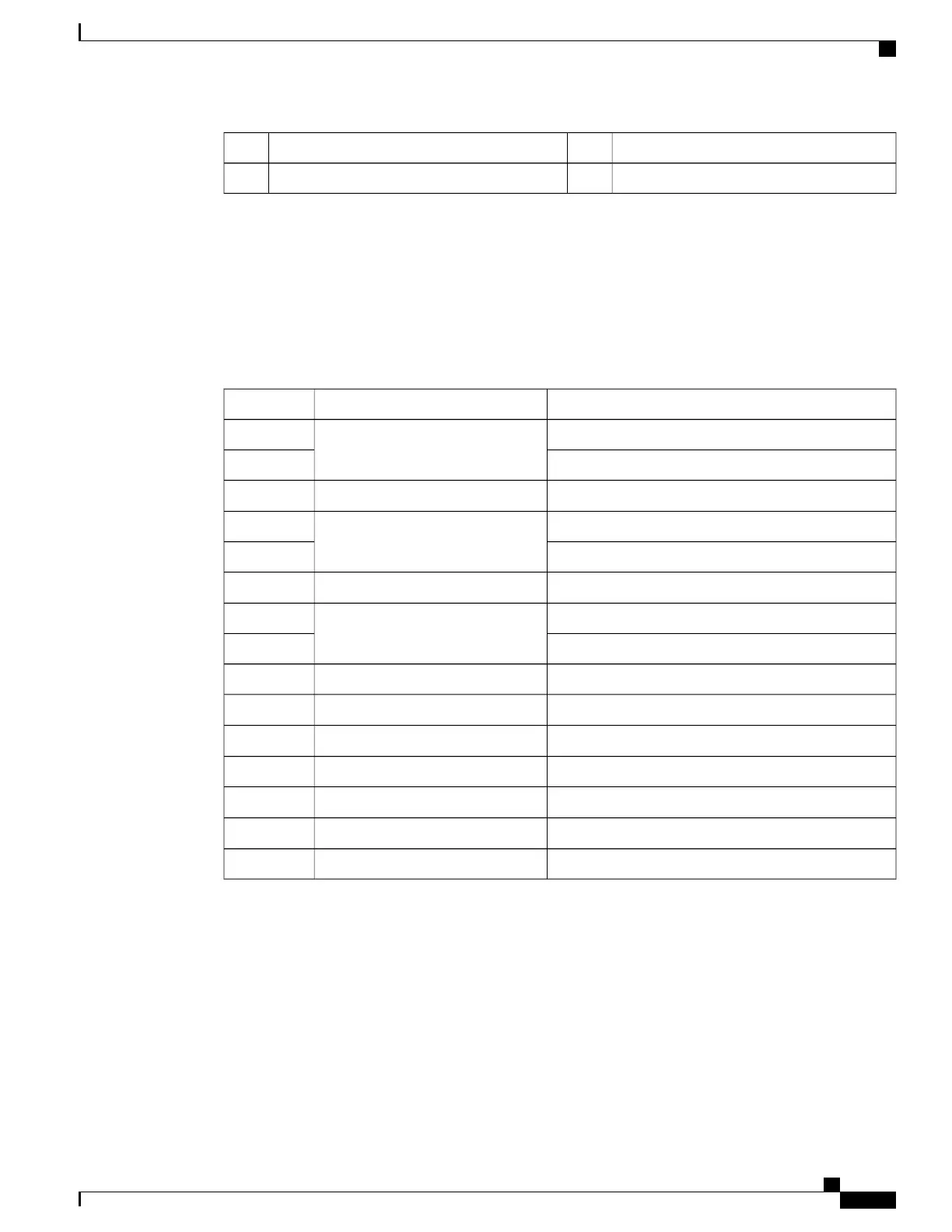
Alarm Connector Pinout
The CO alarm connector pinout is provided in the table below.
Use a Phillips #1 screwdriver to remove the two screws that secure the cover plate over the alarm connector.
Table 14: DB15S CO Alarm Connector Pinout
SignalAlarm LevelPin
Normally OpenMinor1
Normally Closed2
Not connected
—
3
Normally OpenMajor4
Normally Closed5
Not connected
—
6
Normally OpenCritical7
Normally Closed8
Minor, CommonMinor9
Not connected
—
10
Not connected
—
11
Major, CommonMajor12
Not connected
—
13
Not connected
—
14
Critical, CommonCritical15
Electrical Characteristics
Each of the three dry-contact, Form C relay switches is rated to support a maximum switching current of
1A@30VDC.
ASR 5500 Installation Guide
75
SSC Alarm Cabling
Alarm Connector Pinout
 Loading...


