12-27
Cisco Catalyst Blade Switch 3120 for HP Software Configuration Guide
OL-12247-01
Chapter 12 Configuring VLANs
Configuring VLAN Trunks
Load Sharing Using STP Path Cost
You can configure parallel trunks to share VLAN traffic by setting different path costs on a trunk and
associating the path costs with different sets of VLANs, blocking different ports for different VLANs.
The VLANs keep the traffic separate and maintain redundancy in the event of a lost link.
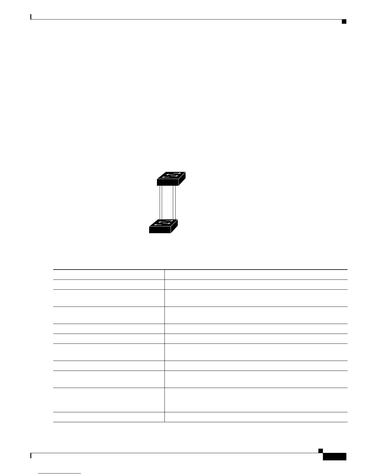
In Figure 12-5, Trunk ports 1 and 2 are configured as 100BASE-T ports. These VLAN path costs are
assigned:
• VLANs 2 through 4 are assigned a path cost of 30 on Trunk port 1.
• VLANs 8 through 10 retain the default 100BASE-T path cost on Trunk port 1 of 19.
• VLANs 8 through 10 are assigned a path cost of 30 on Trunk port 2.
• VLANs 2 through 4 retain the default 100BASE-T path cost on Trunk port 2 of 19.
Figure 12-5 Load-Sharing Trunks with Traffic Distributed by Path Cost
Beginning in privileged EXEC mode, follow these steps to configure the network shown in Figure 12-5:
90573
Switch A
Switch B
Trunk port 1
VLANs 2 – 4 (path cost 30)
LANs 8 – 10 (path cost 19)
Trunk port 2
VLANs 8 – 10 (path cost 30)
VLANs 2 – 4 (path cost 19)
Command Purpose
Step 1
configure terminal Enter global configuration mode on Switch A.
Step 2
interface gigabitethernet1/0/1 Define the interface to be configured as a trunk, and enter interface
configuration mode.
Step 3
switchport trunk encapsulation
{isl | dot1q | negotiate}
Configure the port to support ISL or IEEE 802.1Q encapsulation. You
must configure each end of the link with the same encapsulation type.
Step 4
switchport mode trunk Configure the port as a trunk port. The trunk defaults to ISL trunking.
Step 5
exit Return to global configuration mode.
Step 6
Repeat Steps 2 through 5 on a second interface in Switch A or in the
Switch A stack.
Step 7
end Return to privileged EXEC mode.
Step 8
show running-config Verify your entries. In the display, make sure that the interfaces are
configured as trunk ports.
Step 9
show vlan When the trunk links come up, Switch A receives the VTP information
from the other switches. Verify that Switch A has learned the VLAN
configuration.
Step 10
configure terminal Enter global configuration mode.