20-8
Cisco Catalyst Blade Switch 3120 for HP Software Configuration Guide
OL-12247-01
Chapter 20 Configuring Flex Links and the MAC Address-Table Move Update Feature
Configuring Flex Links and MAC Address-Table Move Update
Configuring VLAN Load Balancing on Flex Links
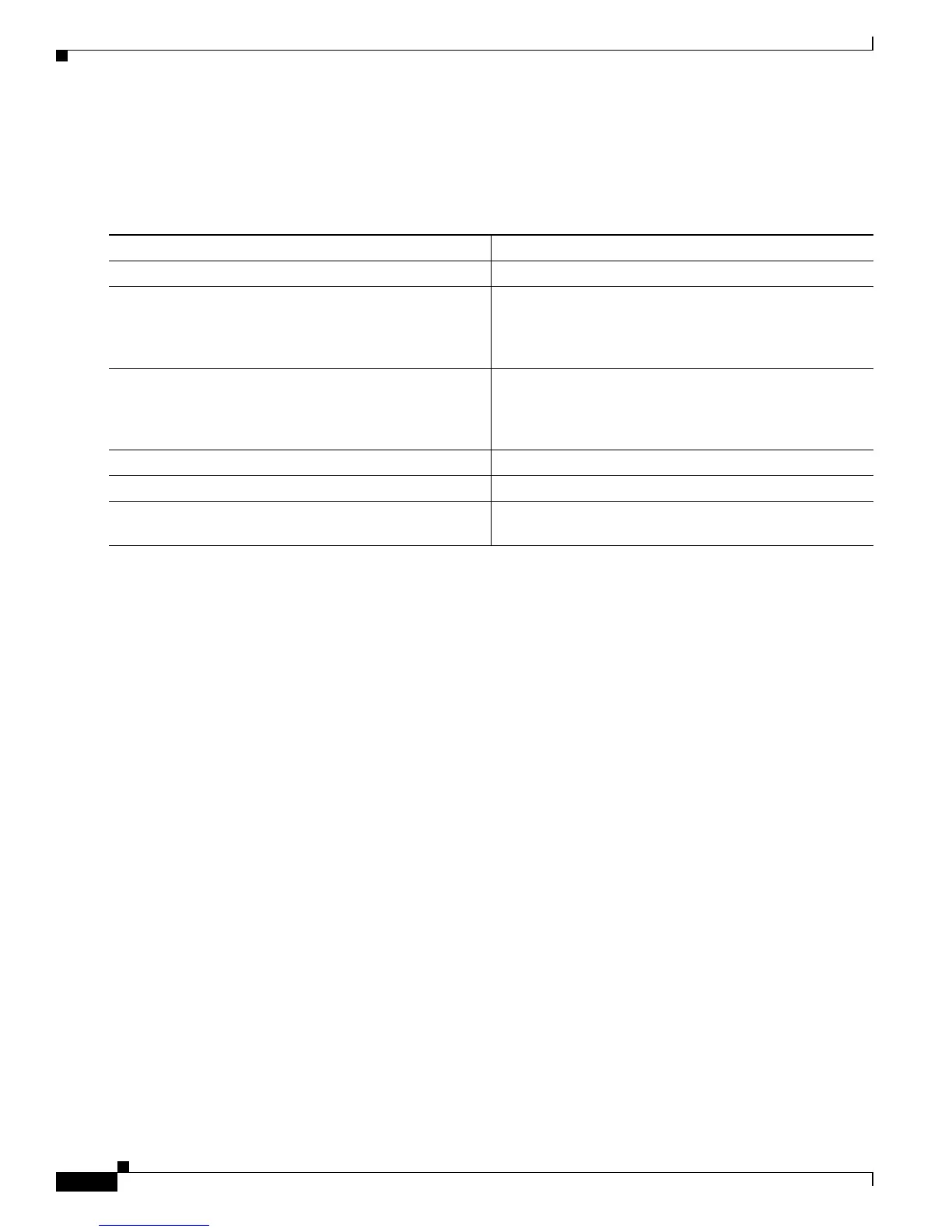
Beginning in privileged EXEC mode, follow these steps to configure VLAN load balancing on Flex
Links:
To disable the VLAN load balancing feature, use the no switchport backup interface interface-id
prefer vlan vlan-range interface configuration command.
In the following example, VLANs 1 to 50, 60, and 100 to 120 are configured on the switch:
Switch(config)#interface gigabitethernet 2/0/6
Switch(config-if)#switchport backup interface gigabitethernet 2/0/8 prefer vlan 60,100-120
When both interfaces are up, Gi2/0/8 forwards traffic for VLANs 60 and 100 to 120 and Gi2/0/6
forwards traffic for VLANs 1 to 50.
Switch# show interfaces switchport backup
Switch Backup Interface Pairs:
Active Interface Backup Interface State
------------------------------------------------------------------------
GigabitEthernet2/0/6 GigabitEthernet2/0/8 Active Up/Backup Standby
Vlans Preferred on Active Interface: 1-50
Vlans Preferred on Backup Interface: 60, 100-120
When a Flex Link interface goes down (LINK_DOWN), VLANs preferred on this interface are moved
to the peer interface of the Flex Link pair. In this example, if interface Gi2/0/6 goes down, Gi2/0/8 carries
all VLANs of the Flex Link pair.
Switch# show interfaces switchport backup
Switch Backup Interface Pairs:
Active Interface Backup Interface State
------------------------------------------------------------------------
GigabitEthernet2/0/6 GigabitEthernet2/0/8 Active Down/Backup Up
Vlans Preferred on Active Interface: 1-50
Vlans Preferred on Backup Interface: 60, 100-120
Command Purpose
Step 1
configure terminal Enter global configuration mode.
Step 2
interface interface-id Specify the interface, and enter interface configuration
mode. The interface can be a physical Layer 2 interface or
a port channel (logical interface). The port-channel range
is 1 to 48.
Step 3
switchport backup interface interface-id prefer vlan
vlan-range
Configure a physical Layer 2 interface (or port channel)
as part of a Flex Links pair with the interface and specify
the VLANs carried on the interface. The VLAN ID range
is 1 to 4094.
Step 4
end Return to privileged EXEC mode.
Step 5
show interfaces [interface-id] switchport backup Verify the configuration.
Step 6
copy running-config startup config (Optional) Save your entries in the switch startup
configuration file.