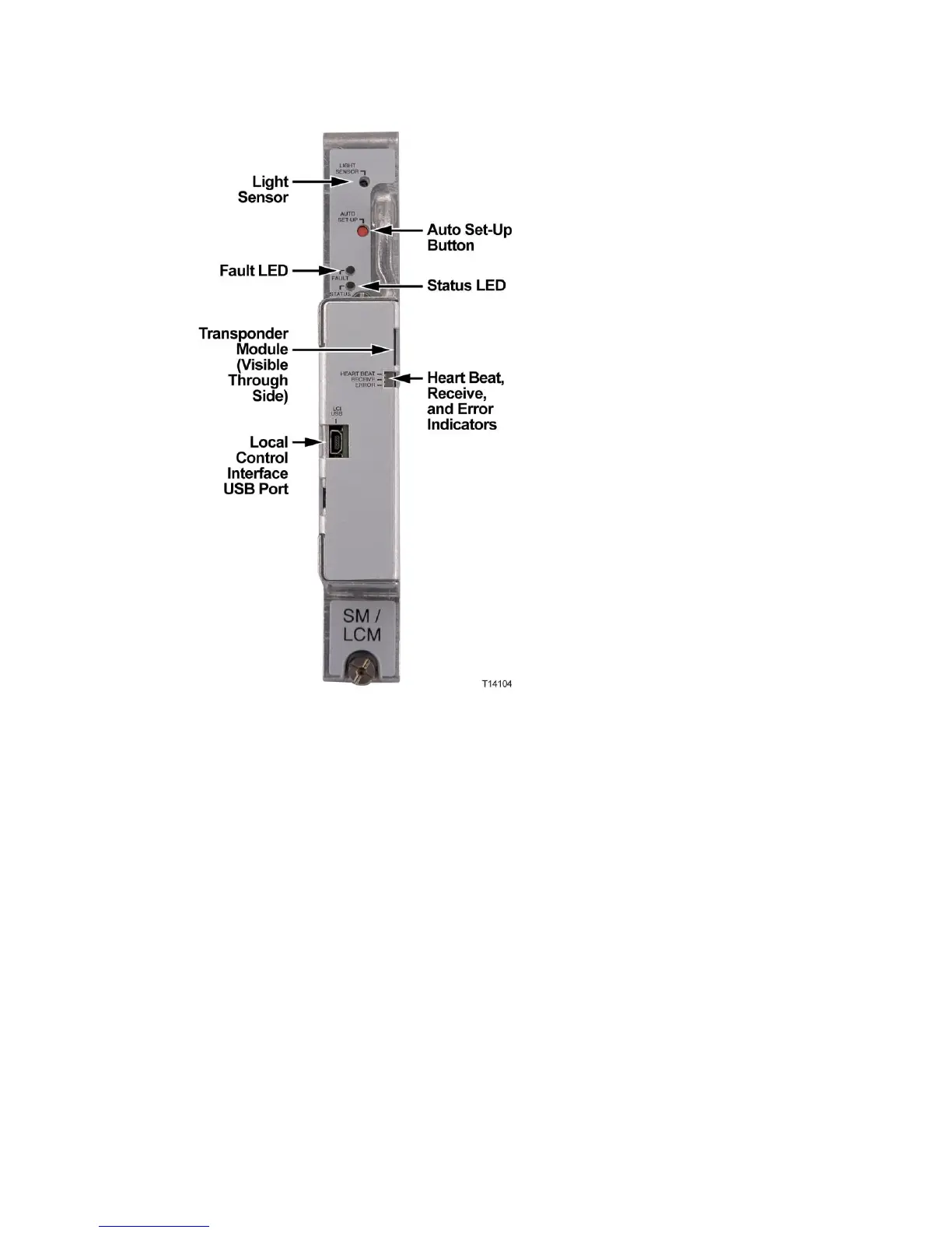
Note: The transponder core module can be seen through the Heart
Beat/Receive/Error indicator cutout in the cover.
Local Control Module Description
The local control module locally monitors the following hub voltages and signals:
AC power presence and peak voltage (for split AC powering cases, AC
power from both sides of node housing is monitored)
DC voltages from both primary and redundant power supplies
Optical amplifier operating parameters
Optical switch operating parameters
The local control module is equipped with a USB port to allow local control of the
optical switches and optical amplifiers through the PC-based GS7000 ViewPort
software. All parameters monitored by the local control module can be displayed
and reviewed using ViewPort.
 Loading...


