Optical Amplifier Power In and Power Out Test
Point Use and Operation
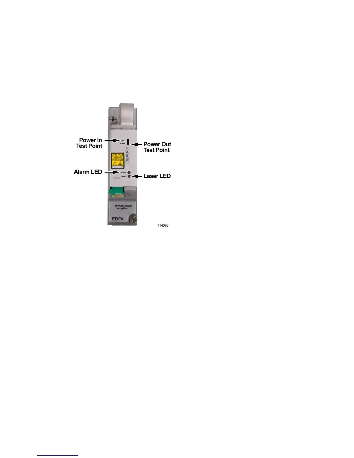
The EDFA modules have test points that can be used to monitor input and output
power levels when the units are in service.
The Power In test point provides a voltage proportional to the optical input power to
the EDFA module. The Power Out test point provides a voltage proportional to the
optical output power from the EDFA.
These voltages can be measured using a DC voltmeter (or DCV function on a
multimeter) and applied to simple formulas to confirm nominal input and output
power.
Power In Measurement
1 Place the positive (+) lead of a DC voltmeter on the Power In test point.
2 Place the negative (-) lead of the DC voltmeter on ground.
Note: When installed, the metal case of the EDFA module is at ground.
3 Record the voltage measurement and apply this formula:
Pin (dBm) = 8 * (Vin (volts) - 2.5)
For example, if Vin measures 3.1 V, the input power to the EDFA is
approximately 8 * (3.1 - 2.5) = 8 * 0.6 = 4.8 dBm.
Note: Results are accurate to ± 0.5 dB at room temperature.
 Loading...


