Housing Lid Fiber Optic Cable Installation - Active
Modules
Overview
The Model GS7000 Optical Hub housing comes with six fiber cable entry ports, two
on the lid and four on the base. The lid ports utilize a standard 4 to 12 count fiber
service cable (FSC) connecting the actives modules, such as EDFAs and optical
switches, to the fiber closure. The base ports utilize a 24 to 48 count MPO
(multi-fiber push-on) FSC for connection between the passive modules and the fiber
distribution plant feeding nodes. Refer to Housing Base Fiber Optic Cable
Installation - Passive Modules (on page 28) for instructions on housing base FSC
installation.
The Model GS7000 Optical Hub can accept a fiber optic cable connector for the active
modules in the housing lid from either the left side (port F1) or right side (port F2) of
the housing, or both. The fiber optic cable(s) carries forward and reverse optical
signals.
This procedure assumes a specific type of connector as an example. Your connector
may be different from the one shown in these illustrations. Be sure to install the
connector according to the connector manufacturer’s instructions.
Important: Fiber optic cable installation is a critical procedure. Incorrect
installation can result in severely degraded performance. Be sure to carefully
follow fiber connector manufacturer’s instructions. See Care and Cleaning of
Optical Connectors (on page 103).
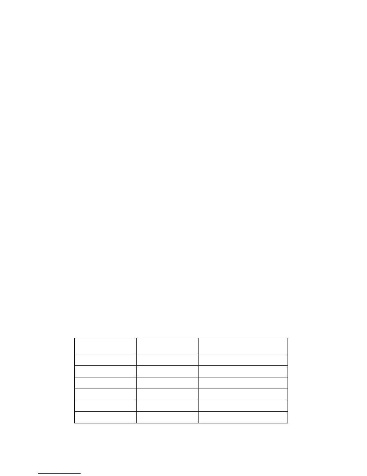
FSC Color Code and Assignment
Fiber connectors and adapters are labeled with the following color code.
Note: This is only a suggested setup. Your fiber assignment may be different.
Refer to your network diagrams to verify your color code.
 Loading...


