3 Loosen the strand clamp bolts to separate the clamps enough to insert the strand,
but do not remove them. Then lift the housing into proper position on the
strand.
4 Slip the clamps over the strand and finger-tighten the clamp bolts. This allows
additional side-to-side movement of the housing as needed.
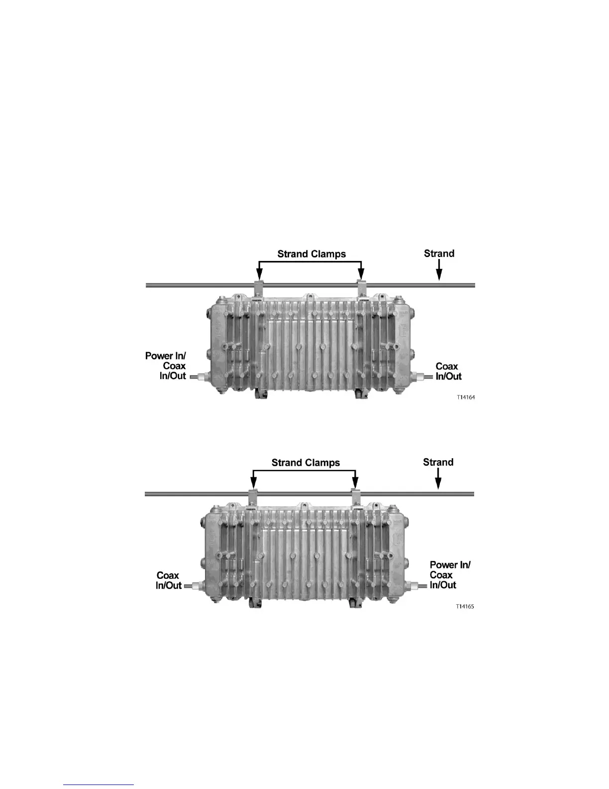
5 Move the housing as needed to install the coaxial cable and connectors. See the
illustrations below for an example.
Powered from Left
Powered from Right
Note: If supplying power to the housing through a main output port, a power
inserter must be installed to inject the AC voltage onto the RF signal.
 Loading...


