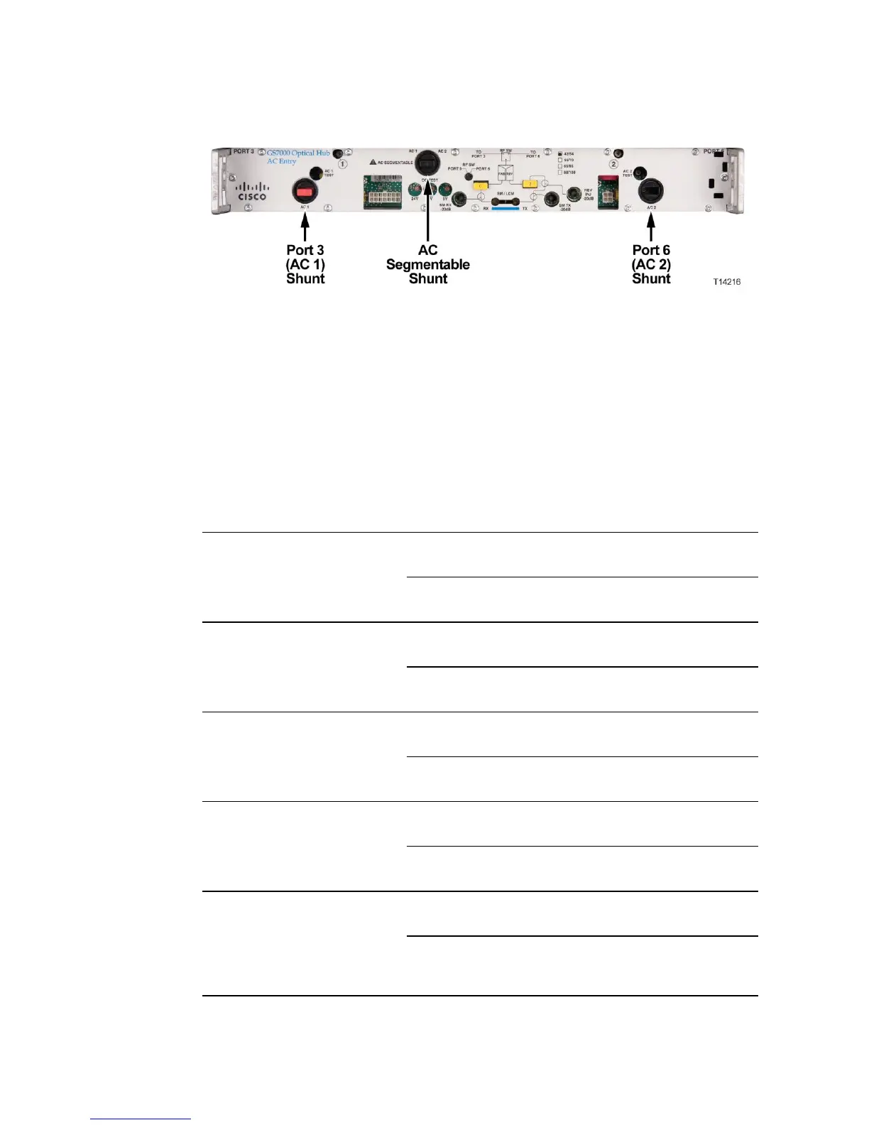
Applying Power to the Hub
Note: Shunts are available with both red and black tops. Use red to indicate
that power is applied to that port. Use black to indicate that input power is not
applied, but passed. Remove shunts to block AC power at the individual ports.
3 The next step depends on how many power supplies are installed and whether
or not you want power to pass through the hub. Use the following table to
determine the proper shunt installation.
a single AC/DC power supply
is installed in slot 2 as the
Primary power supply and
power is applied to Port 3 only
a single AC/DC power supply
is installed in slot 2 as the
Primary power supply and
power is applied to Port 6 only
dual AC/DC power supplies
are installed and power is
applied to Port 3 only
dual AC/DC power supplies
are installed and power is
applied to Port 6 only
dual AC/DC power supplies
are installed and power is
applied to Port 3 and to Port 6
(Configuration Not
Allowed)
Note: "X" indicates a shunt is installed in that location.
 Loading...


