Page 9 | 53
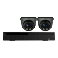
Chapter 2: NVR Appearance
2.1 Front Panel
Table 2-1
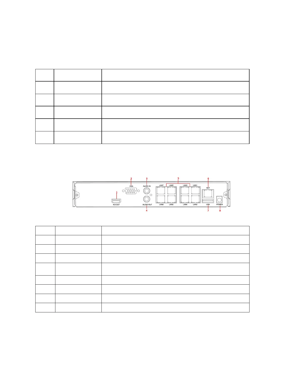
2.2 Rear Panel
Rear panel diagram for ClareVision NVRs
3
Figure 2-3
Connects to HD display devices such as computer monitors
Connect to VGA display devices such as computer monitors
Equipment audio input interface
4 Audio output Equipment audio output interface
Connects IP devices and power IP devices and networks
Connects Ethernet to the network
Allows connection to the mouse or U disk or removable hard disk
No.
Name
Description
1
Switch
the device on/off.
2
Hard disk indicator
Displays hard drive connection status.
3
Power Indicator
Illuminates when powered on.
4
Network Indicator
Displays network connection.
5
USB2.0
mouse or USB memory stick backup.