FSG/MTM/001 060511
147
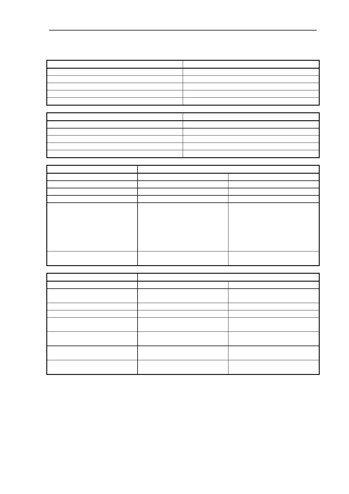
7.2 LED Indicators on Operator Panel
Power LED (Green and Red)
Booting and Power-On-Self-Test: Yellow (Green & Red ON)
Warm Up Green
Power ON (Operating mode) Green
Low Power mode (Sleep mode) Red
Scanner in Test mode (SCANtest 6) OFF
Diagnostic LED (Red)
Booting and Power-On-Self-Test: Red
Warm Up OFF
Normal Operation OFF
Scanner in Test mode (SCANtest 6) Red
Error Condition, see Section 7.3.1 below. Blinking
Wait LED (Yellow) Media Thickness Setting
Normal Extended Thickness
Booting and Power-On-Self-Test: Yellow Yellow
Warm Up Yellow Yellow
Normal Operation: OFF OFF
Automatic update of Light Profile
Correction has been suspended for
a period exceeding the built-in
update-timer or the scanner has
been switched ON with the
Original Guide Plate set for
Extended Thickness.
Blinking
Hint: May also occur during
intensive scanning in batch mode
or if original Exit and Entry
Sensors are both activated during
power on.
Blinking
Hint: Lower Original Guide Plate
to Normal position to allow Light
Profile Correction to be done.
Error Condition, Diagnostic is
blinking, see Section
7.3.1 below.
Blinking
Blinking
Ready LED (Green and Red) Media Thickness Setting
Normal Extended Thickness
Booting and Power-On-Self-Test: Yellow
(Red & Green ON)
Yellow
(Red & Green ON)
Warm Up OFF OFF
No media OFF Red
Media inserted Green Yellow
(Red & Green ON)
Scanning Blinking
Green / OFF
Blinking
Yellow / Red
ATAC mode
(MAGNUM XL 54 only)
Blinking
Yellow / OFF
Blinking
Yellow / OFF
Error Condition: Diagnostic LED is
blinking, see Section
7.3.1 below.
Blinking
Green / OFF
Blinking
Green / OFF or Yellow/Red
7.3 Error Codes
7.3.1 Error Codes displayed on the Operator Panel
A blinking Diagnostic Indicator indicates an error condition. The error may be identified by
an Error Code Number being displayed on the screen and/or by the following combinations of
blinking (F) indicators on the Operator Panel: