FSG/MTM/001 060511
35
3.5 Check and Adjustment of Camera Board, CBE (non Tx and XL models)
All test points referred to are shown in Fig. 3-4, page 37.
All voltages are measured relative to test point GND.
CBE Block Diagram is shown in Fig. 3-5, page 38.
3.5.1 DC Voltages
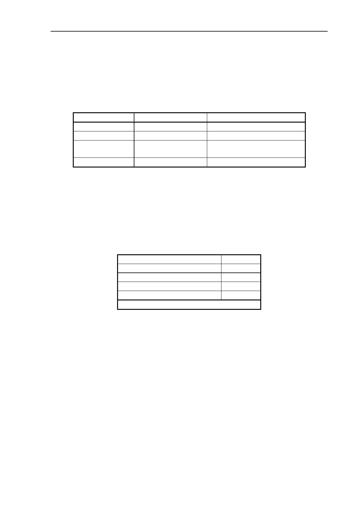
Ref. on Fig. 3-4 DC Voltage Remarks
C46, bottom +5.3 V +0/-0.2 V From SUC / SMPS
C125, top +4.85 V +0.1/-0.2 V Derived from +5.3V on CBE
C14, bottom +12.0 V +1/-0 V From SUC / SMPS, used for
CCD and Camera Motor
C32, right +3.3 V ± 0.1 V From SUC / SMPS
3.5.2 Adjustments
The gain and offset of the CBE-Board are adjusted automatically by running Scanner
Maintenance.
3.5.3 Functional Test
SCANtest 6: Test 7, Complete Hardware Test
3.5.4 Markings
COUGAR 25
CBEAdd
COUGAR 36
CBEAdd
CHAMELEON 25
CBEAdd
CHAMELEON 36
CBEAdd
CHAMELEON PREMIER 36
CBEAdd
where dd = board revision number.
3.5.5 Jumper Settings
No jumpers.
3.5.6 Hints
+3.3 V, +5.3 V, and +12 V is supplied from the SMPS via the SUC-Board.
CCD
The lines of pixels on the CCD are covered by color filters and arranged as follows:
Upper line on the CCD: Blue
Center line on the CCD: Green
Lower line on the CCD: Red
As the image is mirrored an even number of times (mirror chassis and lens), the Blue line
remains upper line when referred to the original.