FSG/MTM/001 060511
30
3.4 Check and Adjustment of Lamp and Motor Driver Board, LME
All test points referred to below are shown in Fig. 3-2, page 33.
All DC voltages are measured relative to test point GND.
LME Block Diagram is shown in Fig. 3-3, page 34.
CAUTION:
The connectors J1, J2, J4 and all the components on the left half of the board are
connected to the line voltage and constitute a risk of electric shock, or injury to persons.
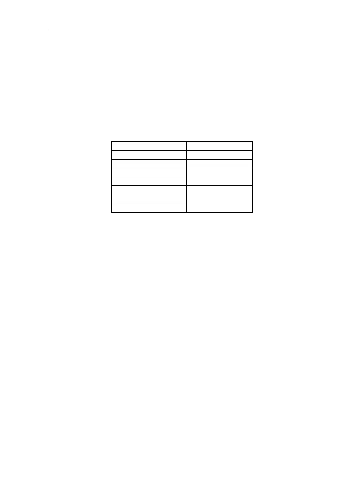
3.4.1 DC Voltages
Ref. on Fig. 3-2 DC Voltage
Test point GND GND
J10, pin4 - GND +5.3 V +0/-0.2 V
J10, pin5 - GND +12.0 V + 1/-0 V
J10, pin6 - GND +24.0 V ± 1 V
TP9 - GND -5.0 V ± 0.5 V
TP3 – TP4 * +200 V ± 20 V
TP5 – TP4 *
−200 V ± 20 V
* Caution: These test points are at high voltage level and constitute a risk of electric
shock, or injury to persons.
3.4.2 Lamp-Driver Adjustment
Because of higher demands to the light level in later scanners, the general specification for the
lamp driver adjustment has been changed. This change applies to all scanner models covered
by this TSM.
The former specification where the voltage on TP7 from time to time was readjusted to a
certain level gradually lowered the light level in the scanner. This is because the voltage on
TP7 increases with lamp aging to compensate for drop in lamp efficiency. Or in other words,
the older the lamp, the higher the voltage on TP7 for the same light level. The voltage on TP7
will therefore slowly increase over time and if readjusted the light level is lowered.
To ensure a constant predefined light level in the scanners throughout the lifetime of the
lamp, the lamp driver should therefore ONLY be adjusted when the lamp is new. In this way
the light level is kept at a known predefined level.
This means that the lamp driver is ONLY adjusted when changing either:
• the Lamp
• the Lamp Driver Board, LME
• the Lamp Sensor Board, OSB
and in order to do so the lamp MUST be new
Always replace the lamp before replacing the Lamp Driver Board