FSG/MTM/001 060511
15
The scanlines from the individual cameras are mechanically aligned (by means of a small
electric motor) in the vertical direction. The Vertical Alignment and the Horizontal Stitching
may be done automatically by means of either SCANtest 6, Test 11 or as part the Scanner
Maintenance calibration procedure.
2.4 MAGNUM XL 54
The Block Diagram is shown in:
Fig. 2-6 MAGNUM XL 54 Block Diagram, page 23
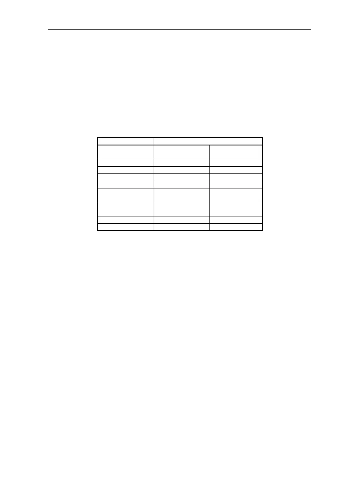
The XL 54 scanner range consists of:
Model: GH67D
Trade name:
MAGNUM XL 54
MAGNUM XL 54
PLUS
No. of cameras:
4 4
Chassis:
54 inches 54 inches
Scan width:
54 inches 54 inches
Scanner Controller:
SUCH SUCH
Computer
interface:
IEEE 1394/SCSI
(IMDA)
IEEE 1394/SCSI
(IMDA)
Scan mode:
Color
Monochrome
Color
Monochrome
Optical resolution:
508 dpi 508 dpi
SmartCard:
BASIC PLUS
Model GH67D is marketed with two different levels of functionality, such as image
resolution, scanning speed, scanning modes, etc:
Model: GH67D (IEEE 1394 and SCSI interface)
Trade names: MAGNUM XL 54 (basic level of functionality)
MAGNUM XL 54 PLUS (enhanced level of functionality)
The basic version of the scanner (MAGNUM XL 54) may be field upgraded to the enhanced
version (MAGNUM XL 54 PLUS) by replacing the BASIC Smart Card with a PLUS Smart
Card.
The Automatic Thickness Adjustment Control (ATAC) automatically adjusts for media
thickness up to 0.6 inch (15 mm). The motor driver board (MDA) and the motor for the
ATAC system are located in a non-removeable Original Guide Plate.
The scan-area is illuminated by one white fluorescent lamp. The light output from the lamp is
stabilized by feedback to the lamp power supply board (LME).
Each CCD-Camera in the scanner contains one 7500 x (3+1) pixel (RGB Triplets +
Panchromatic B/W) CCD. The output signals from the CCDs are Light Profile Corrected at
pixel level.
All scanning and image processing functions are contained on only two boards, the Camera
Board (CBF) and the Controller Board (SUC).
The computer Interface Module (IMD) contains:
 Loading...