FSG/MTM/001 060511
27
3.3 Check and Adjustment of the Switch Mode Power Supply, SMPS
All test points referred to below are shown in Fig. 3-1, page 29.
All DC voltages are measured relative to CN3, pin 1, 2, 3, 4, 5 (GND).
3.3.1 AC Voltages
CAUTION:
The connector CN1 is connected directly to the line voltage and constitute a risk of
electric shock, or injury to persons.
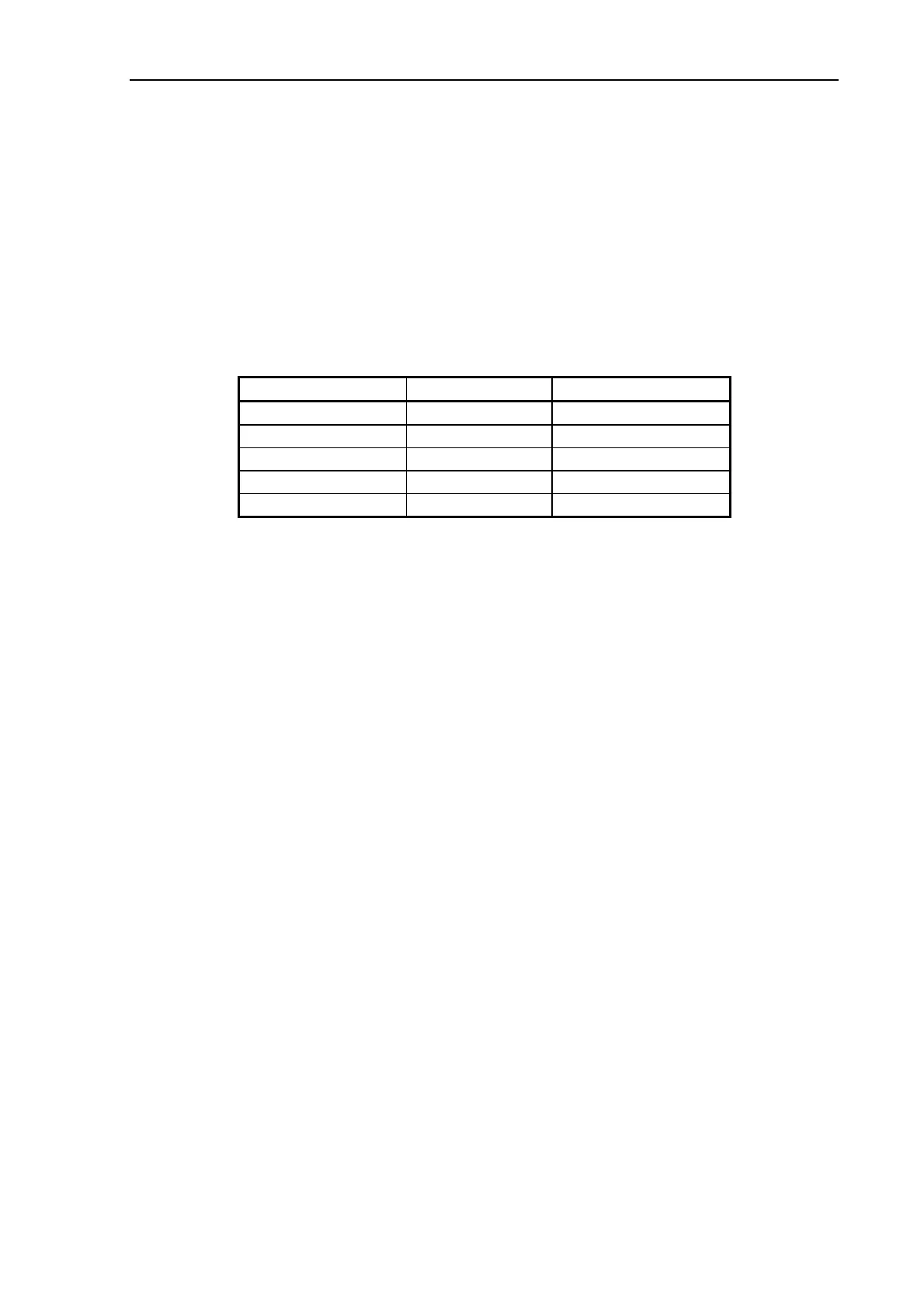
3.3.2 DC Voltages
Ref. on
Fig. 3-1 Ref. on SMPS DC Voltage
CN3,pin 6,7,8 3.3V +3.3 V ± 0.1 V
CN3,pin 1,2,3,4,5 G GND
CN2,pin 3,4,5 5V +5.3 V +0/-0.1 V
CN2,pin 2 V3 +12 V + 1/-0 V
CN2,pin 1 V4 +24 V ± 1 V
3.3.3 Adjustments
CAUTION:
The output voltages of the SMPS are all factory set and should normally not be
adjusted.
The (5V) output voltage should be no more than 5.3 V measured between GND and CN2, pin
3,4,5 (5V) on the SMPS, and no less than 5.1 V measured between GND and C46, bottom on
the CBE-Board respectively C918, bottom on the CBF-Board.
If the voltage is not within these limits, it may be adjusted by potentiometer SVR1 on the
SMPS, see Fig. 3-1, page 29.
3.3.4 Fuses
The type and rating of the fuse on the SMPS is:
F1: F4A type IEC 127-2/2, UL R/C
CAUTION:
For continued protection against risk of fire, replace only with same type and rating of fuse.
3.3.5 Markings
No marking.
3.3.6 Jumper Settings
No jumpers.
 Loading...