Chapter III – Subassemblies
3-65
C
996-0255 rev. b
Chapter III Subassemblies & Module Descriptions
G. CB600C series simmer capacitor banks
mini index
CB634C front & rear panels p. 3-66
Wiring diagram, CB630C p. 3-72
SCR PCB schematic p. 3-73
Current board schem. p. 3-74 & 75
Trigger schematic p. 3-76 & 77
HV input schem. p. 3-78
Wiring diagram, CB634C p. 3-79
.7/1.4A current PCB p. 3-81
1. General Description
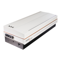
The Continuum simmer capacitor banks are designed for use in
Continuum’s line of high repetition rate laser systems. The capacitor
banks store the energy needed to run the flashlamps. The H series capaci-
tor banks are compatible with the C series power units.
They also convert the 24 volt trigger pulse from a power unit to a high
voltage spike to initiate ionization in the flashlamps. Safety interlocks
ensure that the cable to the laser bench is firmly connected.
2. Structural Organization
When you open a Continuum capacitor bank, the main capacitor is
mounted in the middle of the chassis (see page 3-70). The trigger board is
standing on its side in the left of the chassis next to a large transformer. In
the right rear corner of the chassis are the power relay, rf line filter and
fuses. The laser head cable comes in through the rear panel.
In the rear of the chassis is the high voltage PCBA. The function of this
circuit board is to isolate the power unit from the high voltage capacitor
and discharge the capacitor in the absence of the +24V. Discharge time
through the dump resistors is <10 ms, but in the event of a failure of this
circuit, a permanently mounted 10 MΩ resistor will discharge the capaci-
tor in ~1 minute. Whenever working on the system, safety precautions
should be taken to ensure that there is no residual voltage on the capaci-
tors.
At startup the power relay opens allowing the CB to charge, and then at
shutdown the capacitors discharge through resistors. This is done at
shutdown to assure that there is no hold-over energy left in the capaci-
tors.

 Loading...