7
At the nodal points of the standing wave within the gain media the electric field vector is zero
and hence no stimulated emission can occur. Since significant energy storage and gain can remain
at these nodal points, light of such frequency as to have a non-zero field at the other frequency’s
nodal points can exceed threshold for lasing. The above describes the situation within a seeded host
at the time of output pulse emission.
Consequently, the host would be expected to exhibit evidence of spatial hole burning (ie.
multimode operation) unless the spatial hole burning is somehow suppressed. In practice these
effects are indeed observed and the classic way of suppressing spatial hole burning is to ensure that
the polarizations of the counterpropagating waves are orthogonal within the gain media
5
. This is
conveniently achieved in the host resonator by surrounding the Nd:YAG rod with a pair of quarter-
wave plates oriented so as to yield counter-rotating circularly polarized light within the Nd:YAG
rod.
1.1.6 Frequency Control of the Injection Seeder
The frequency of the seed laser is temperature tunable. By changing the temperature of the
monolithic seed laser crystal, its output can be tuned to the center of the host lasers gain curve. This
position produces the most effective and stable seeding and also the highest seeded output power
from the host laser.
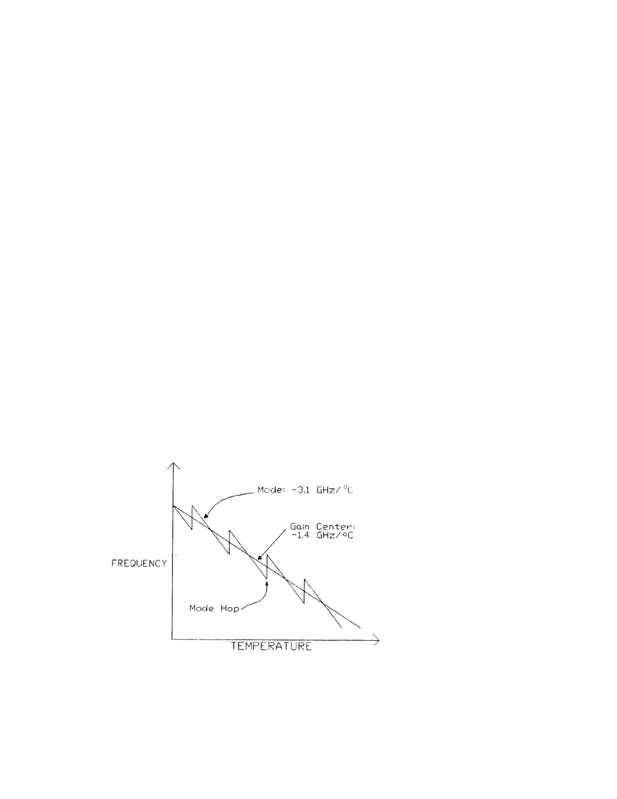
Two temperature effects produce the movement of the seeder output frequency. The first is the
combination of the expansion (or contraction) of the Nd:YAG crystal and the change in the
Nd:YAG refractive index to produce a frequency shift of -3.1 GHz/
°
C in the Seeder resonator
modes. The second is that the movement of the Nd:YAG gain center with temperature causes a
frequency shift of approximately -1.4GHz/
°
C. These two effects combine to produce the frequency
tuning curve shown in Figure 1-7. Note that approximately every 20 GHz the frequency "hops"
back about 10 GHz. This is due to a new longitudinal mode moving to a position closer to the
center of the gain curve of the seed laser.
Figure 1-7: Frequency Tuning of the Injection Seeder