Precision II Operation and Maintenance Manual
C
2-14
996-0255 rev. b
c) DELAYS :
1. A = T + 0
2. B = A + 10 µs
3. C = A + 200 µs
4. D = C + 10 µs
2. Start up the Powerlite as follows.
a. Turn On Key switch
b. Select AUTO and Activate PGM#2
c. DO NOT press the START key
3. Locate the External Trigger Panel (ETP) on oscillator side of
laser bench.
4. Connect a BNC cable between the AB positive going output(0V
to 4V for 10 µs) of the DG535 and the EXT FLASHLAMP Trig In
connector on the ETP.
Note:
The laser flashlamps should start flashing at reprate set
on a DG535. The red LED on the ETP next to the Trig In
connector should come on.
5. Flip Q-SWITCH TRIGGER toggle on ETP to “ext” position.
Note:
The red LED on the ETP next to the EXT connector
should come on.
6. Connect a BNC cable between the CD positive going output (0V
to 4V for 10µs) of the DG535 and the Q-SWITCH TRIGGER BNC
connector on the ETP.
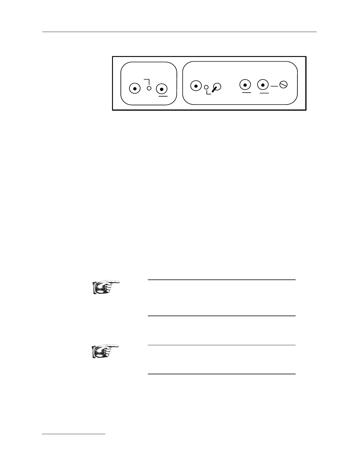
External Trigger Panel (ETP) found on side of bench.
EXT FLASHLAMP
fixed
SYNC OUT
trig in
sync
out
TTL
trigger
diode
photo seeder
variable
Q-SWITCH TRIGGER
int
delay
ext
TTLTTL
TTL
TTL