6
The derivative, ðT
b
/ðL, is developed by slightly changing or "dithering" the cavity length (and
thus the laser output frequency), and measuring the change in the build-up time. The dither is
produced by translating the piezo a small amount from its average position in an alternating fashion.
On the first pulse the resonator is dithered to a slightly shorter length from its average length, and
then dithered to a slightly longer length by the same amount on the subsequent pulse.
The exact frequency of the pulsed laser is determined absolutely by the physical spacing
between its two resonator mirrors
4
. Because of this, the output frequency of the pulsed laser also
will dither in proportion to dither applied to the piezo. Therefore, it is desirable to minimize the
amount of dither required to maintain stable frequency overlap of the seed and pulsed lasers.
The dither necessary to achieve this goal is related to the overall stability of the pulsed laser.
Frequency and energy instabilities in the pulsed laser translates into jitter in the Q-switch build-up
time. This jitter is effectively "noise background" in which must be found the desired Q-switch
build-up time error correction signal. For a typical laser the amount of dither required is typically
less than ±2% of the resonator free spectral range (0.02 * 250 MHz = ±5 MHz). Such an amount of
dither is minimal relative to the 60 MHz Fourier transform limited linewidth of a typical 8 nsec
pulse.
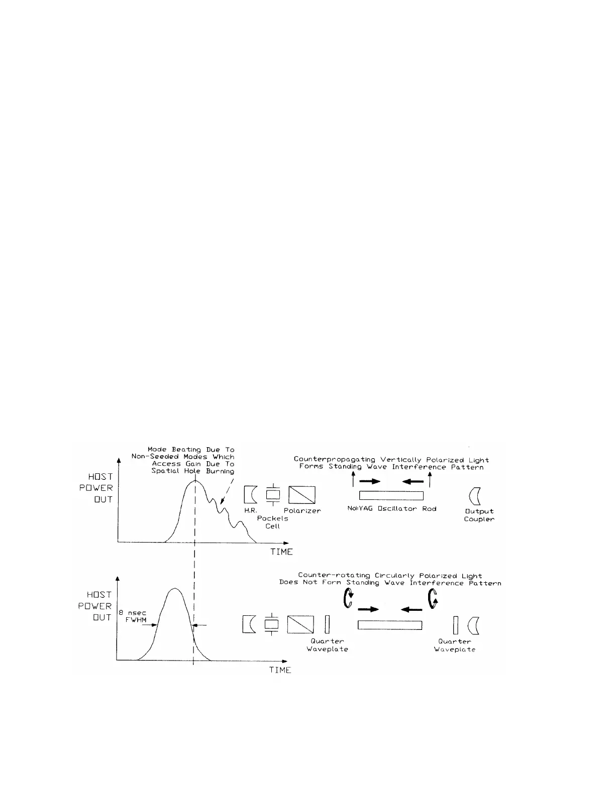
1.1.5 Suppression of Spatial Hole Burning
When two counter-propagating waves of similar intensity and identical polarization and
frequency are present in the same volume they will interfere in a classic standing-wave pattern. At
every one-half wavelength from the fixed resonator mirror reflection points there will be nodes in
the standing wave pattern. The term "spatial hole burning" refers to this phenomena as applied to a
physically fixed gain media such as Nd:YAG. Figure 1-6 depicts this effect.
Figure 1-6: Spatial Hole Burning Effects