Chapter III – Subassemblies
3-47
C
996-0255 rev. b
3. Principle of Operation
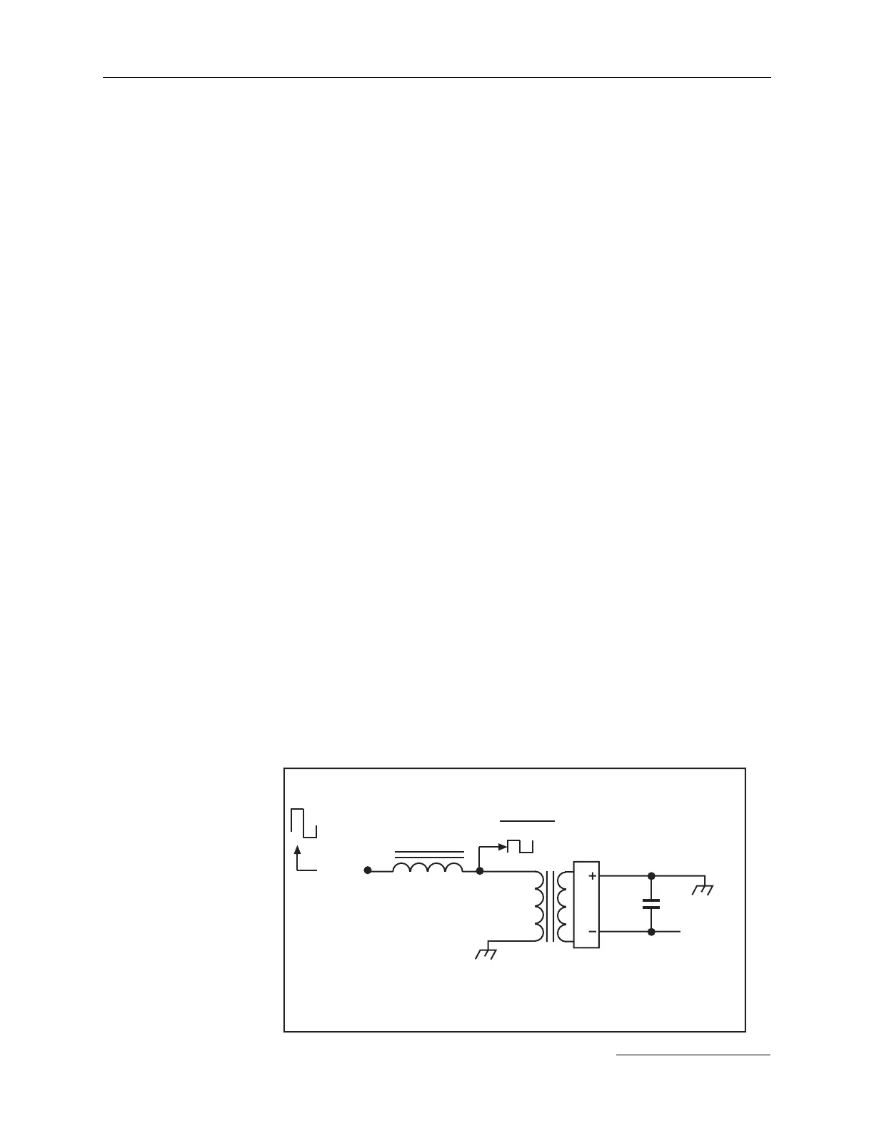
The power units use an off-line reactance-limited dc-dc converter to
provide a controlled charging current to the capacitor bank. The
capacitor(s) in the CB present a low impedance voltage source to the HV
diode bridge whatever the charge voltage. This voltage is commutated by
the HV diode bridge, when an alternating current source is applied -
effectively creating a square wave voltage clamped by the output capaci-
tor. This voltage is matched to the source voltage (the chopped waveform
from the bridge inverter) by the high voltage output transformer. An
inductor “L” is inserted between the inverter and the HV output trans-
former providing the reactance-limiting effect. The E
IN
square wave is
larger than the E
OUT
/transformer ratio square wave (the difference is
inversely proportional to the state of charge in the output capacitor).
Therefore, at zero volts E
IN
appears across L, yielding a triangular current
waveform.
The peak current at zero volts output seen by the inverter is a function of
E
IN
, L and the frequency of the inverter.
As the capacitor charges, the (E
OUT
/transformer ratio) voltage increases
and the voltage across L decreases, causing the current in L to decrease
correspondingly. Thus, for a fixed inverter frequency and fixed E
IN
, L and
the transformer ratio can be chosen to limit the inverter current to a
specific value and provide a current source output to the capacitor bank.
However, the current in L is also directly proportional to E
IN
. If the
frequency is fixed, the circuit would provide very low output power at
low input voltage and excessive output power at high input voltages,
limiting the practicality of the application. Therefore, since the current in
L is inversely proportional to the frequency of the inverter, a voltage-
controlled oscillator (VCO PCBA schematic) is used to provide the
inverter’s clock signal. The VCO derives its control voltage from the dc
voltage feeding the HV converter PCBA(s). As more voltage is available
E (output)
xfmr ratio
E (input)
(from bridge
inverter)
HV
output
xfmr
high
voltage
E (output)
rectified
L
HV diode
bridge
output cap.
Reactance-limiting inductor L.