Precision II Operation and Maintenance Manual
C
3-46
996-0255 rev. b
pulse on the +24 volt accessory
output is for system rep rate syn-
chronization. The function of the
24Vdc supply is to:
• power accessories
• open interlock relays in capacitor
banks
• carry the "24 V to 0 V" synchron-
ization signal to the capacitor banks
for flashlamp triggering.
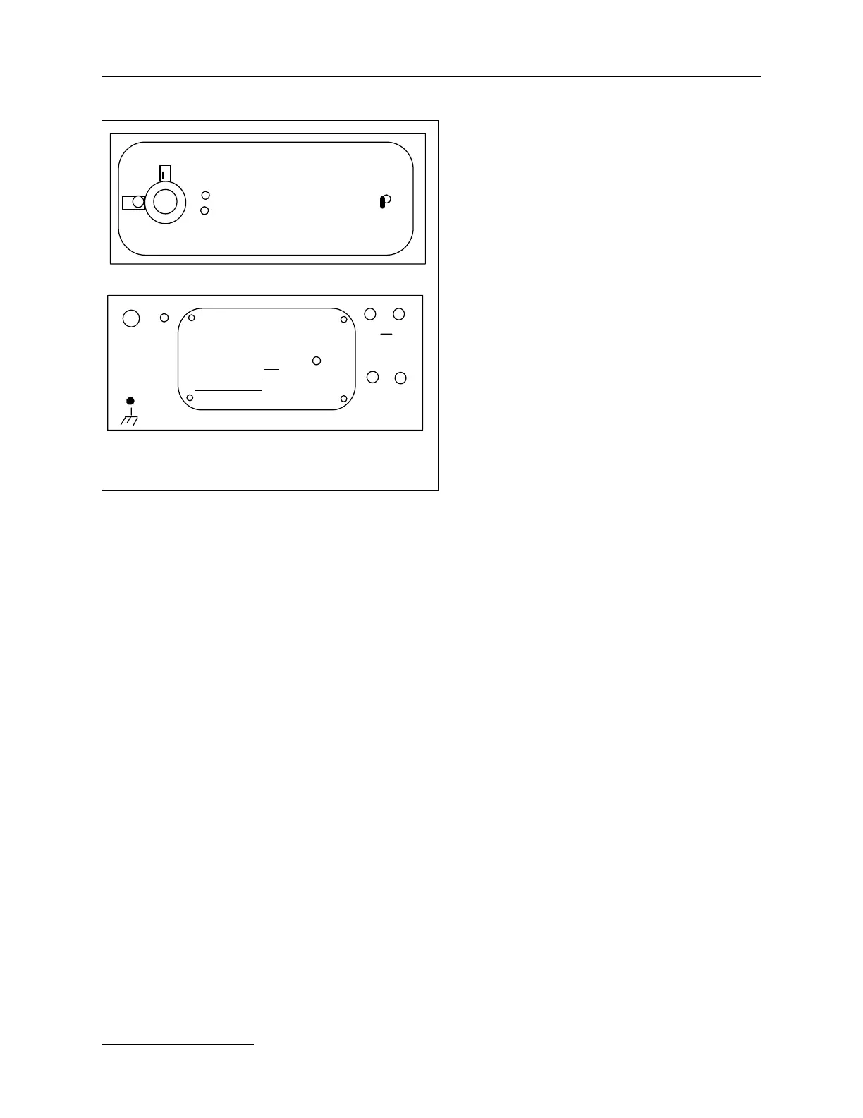
Front Panel
1) POWER ON red indicator light.
This is the main power indicator. It
comes on when the power unit is
activated and line power is present.
2) HV ENABLE red indicator light
shows that the system is in the GO
mode and can be operated.
3) Voltage selector knob. This selects the capacitor bank
charge voltage.
Rear Panel
1) J1 is the main power input of 205-255 Vac 3 phase or 205-
255 Vac single phase 50/60 Hz.
2) J3 is the connection to Control Unit, CU601C. The “J3 to
CU" connector receives the PU enable signal, charge and
firing orders from the control unit. It also sends the end of
charge signal to the CU601C. These units are optically
isolated.
3) J4 is marked “HIGH VOLTAGE output”. This is a high
voltage output which must be connected to the high
voltage input of the capacitor bank. Type of connector:
MHV.
4) J5 & J6 are identical 24V trigger outputs. For each power
unit there are two 24V trigger outputs. One has to be
connected to the J4 or J5 24V input of the capacitor bank
which is charged by this power unit.
5) J7 & J8 sense the simmer status of the “C” version capaci-
tor banks allowing reduced voltage triggering.
Front panel, PU610C/620C
power on
HV enable
PU620C
voltage (kV)
AC power
to
CU
J3
J5 J6
+24V/trig out
220Vac
Rear panel, PU610C/620C
J1
input
J4
HIGH VOLTAGE
output
WARNING
Disconnect all power &
discharge all capacitors
before connecting or
disconnecting J4. Do
not operate without
CB unit connected.
E1
PU610C/620C DO NOT REMOVE SCREWS
HV OUTPUT MODULE
Chassis
gnd
J7 J8
simmer
monitor
from CB (s)
PU610C/620C front & rear panels.
 Loading...