Chapter V – Troubleshooting
5-23
C
996-0255 rev. b
4) Slide mirror 7d until beam is parallel to the side of the
bench and centered on the pinhole.
5) Use mirror 7c to center the beam on the first pinhole and
use mirror 7d to center the beam on the second pinhole.
6) Remove the pinholes.
7) Turn the oscillator back up to normal operating energy.
8) Adjust mirror 7c for a symmetric beam, looking with
orange fluorescent paper just after the second amplifier.
9) Move the orange paper out to the beam dump and adjust
mirror 7d to eliminate any caustic.
10) Repeat steps 8 and 9 until the beam image looks good at
both places. Turn on the amplifiers and confirm that they
are aligned.
11) Install and adjust the quartz rotator (see procedure be-
low).
12) Install and adjust apertures so that they are centered on
the input IR.
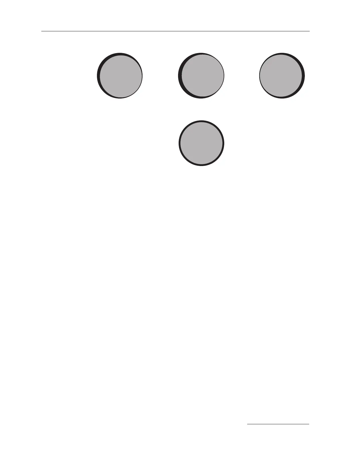
low and to the right vertical align. is good, but is still
to the right
overcorrected to right
alignment correct & centred
Amplifier alignment burn patterns.