28
SECTION 3: OPERATION
3.1 CONTROL PANEL
The key operational procedures in the use of the injection seeding system involve the
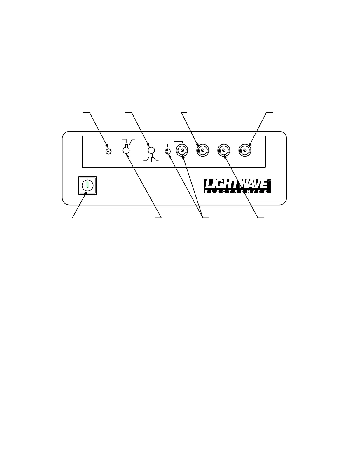
controller’s front panel (control panel). The control panel is shown in Figure 3-1, while descriptions
of the various features follow.
SEEDER
CONTROL
MNL
AUTO
DSBL
STBY ON
ON
ON
FREQ
OFFSET
PIEZO
VOLT
QSW
BLD UP TIME
RESET
Emission
Indicator
Control
Switch
Key
Switch
Mode
Switch
Reset Indicator
and BNC
Frequency BNC
Piezo BNC
Build-up Time
BNC
Figure 3-1: Control Panel of Controller
3.1.1 Key Switch
The Key Switch should be turned to the ON position in order to supply electricity to the seed
laser’s head and control electronics. The seed laser cannot emit radiation unless the key is turned to
the ON position. Turning the Key Switch to the ON position does not necessarily imply the laser is
emitting radiation, since the laser may be in the Standby Mode or the aperture shutter may be
closed. There is a 15 second delay between turning the key switch to "ON" and any possible
emission.
3.1.2 Emission Indicator
The amber emission indicator is illuminated whenever the Control Switch and the Key Switch
are turned to the ON position, and the interlock is closed. After turn-on there is a 3 second delay
before the seed laser emits light.
3.1.3 Control Switch
With the Control Switch in the STANDBY ("STBY") position all temperature control circuits
are operational, but the current to the laser diode is turned off (i.e. the seeder is not lasing). In the
ON position the laser is fully operational. There is a 3 second delay between switching to "ON" and
laser emission.
3.1.4 Mode Switch

 Loading...