22
2.1.6 Piezo Installation
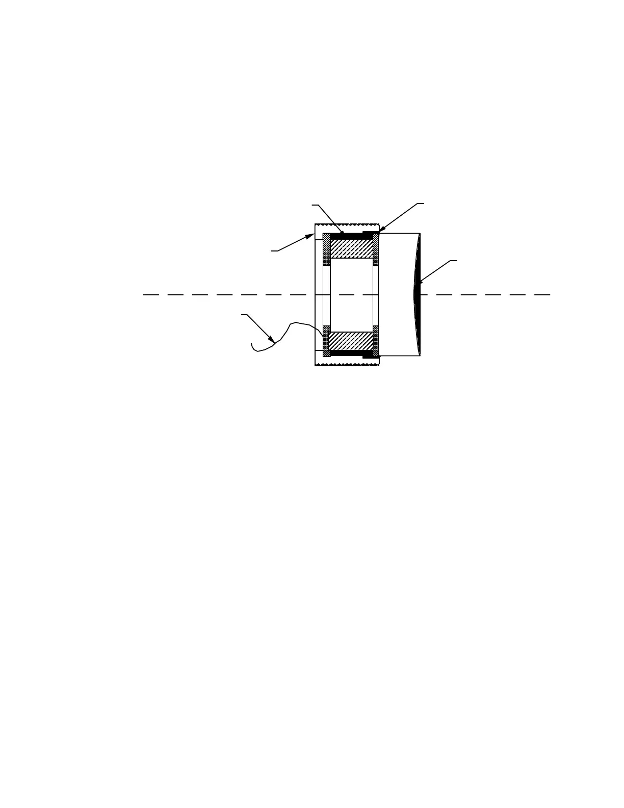
A piezoelectric element is supplied with the seeder, and this piezo should be attached to the
rear reflector of the host laser to control its length (frequency). The piezo assembly as supplied by
Lightwave is shown below in Figure 2-5 (Lightwave does not supply the HR end mirror). A typical
procedure for installing the piezo is given below.
Ceramic Mounting Plates
(2 places)
Mirror and Piezo Holder
(1 1/8"Ø - 28 UNS - 2A)
Piezo Wire
(to seeder electronics)
Piezo Element
Host Laser HR End Mirror
(Customer Supplied - 1" Ø)
Figure 2-5: Piezo Assembly
1. Remove the high reflecting (HR) mirror from its mount by unscrewing the endcap and pulling
the HR mirror out.
2. Glue the HR End Mirror to the Ceramic Mounting Plate which is away from the piezo wire.
Ensure the mirror is well centered on the ceramic plate and does not extend beyond the
edges of the ceramic plate.
3. Place the Piezo Element (with HR end mirror attached) into the Mirror and Piezo Holder.
Ensure there is no interference between the HR End Mirror and Mirror and Piezo Holder.
4. Install the Mirror and Piezo Holder (with Piezo Element and HR End Mirror) in the host laser.
5. Route the Piezo Wire to the seeder’s laser head, and plug it into the "PZT" input.
6. Realign the resonator as appropriate. Normally it is not necessary (nor desirable) to adjust the
output coupled mirror.
7. With the host laser running at its standard operating energy, optimize the alignment by adjusting
only the HR End Mirror.