Precision II Operation and Maintenance Manual
3-6
C
996-0255 rev. b
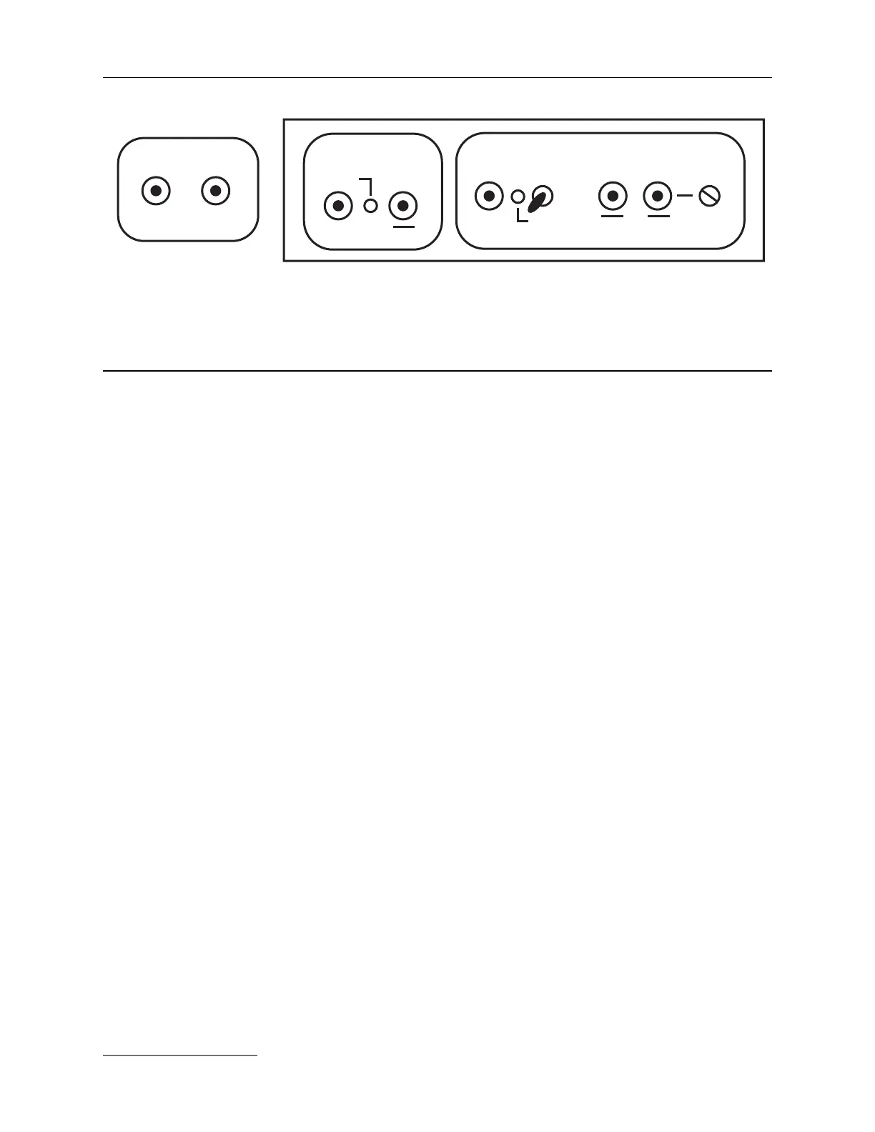
Precision control panel & External Trigger
Panel (ETP) found on side of bench.
B. Laser bench electronics
1) Bottom view of laser bench
On the bottom of the laser bench are some electrical connections that are
not visible when laser is operating. They are the 750 V board and the
crystal oven wiring shown here. Below is a view of the underside of the
bench with these components and the positioning of the hoses and um-
bilical.
2) Precision II external controls
The CU601C EXTERNALS 9-pin ‘D’ connector is routed to the sync panel
in the Precision II . This allows direct control of flashlamp and Q-switch
firing via BNC connections to TTL level signals. The normal fixed and
variable sync functions also appear as TTL level BNC connections on the
sync panel.
To operate in external mode, the system must be placed in a passive
configuration by the remote box or RS232 in order to allow complete
control of the laser. In this configuration, the CU601C monitors the status
of the system interlocks, and enables laser operation via the keyswitch. It
is entirely passive as far as the flashlamp and Q-switch are concerned.
(The shot counter is inoperative for externally triggered flashlamp shots.)
a) External flashlamp triggering via the TRIG IN BNC —
Positive going TTL pulses at 10 Hz or greater repetition
rate will commence triggering the flashlamp starting at
the second pulse, and will illuminate the red LED TRIG
IN status indicator. (Repetition rates below 10 Hz are
electrically locked out.).
b) Flashlamp sync via the SYNC OUT BNC connector —
Negative going TTL pulses appear at the BNC connector
at the beginning of each actual flashlamp current pulse.
The flashlamp sync signal is derived from a toroidal
current transformer through which the oscillator
flashlamp high voltage lead is passed. The flashlamp sync
Q-SWITCH TRIGGER SYNC OUT
EXT FLASHLAMP
TTL
TTL
int
ext
fixed
variable
delay
trig in
sync
out
photo seeder
diode trigger
TTL TTL
TTL