Chapter III – Subassemblies
C
3-83996-0255 rev. b
Chapter III Subassemblies & Module Descriptions
H. Cooling Group, CG604C
mini index
Cooling requirements graph, 10 & 30 Hz p. 3-86
CG604C wiring dia. p. 3-87
Waterflow diagram p. 3-89
1. General Description
The CG604C cooling group is a rack mounted unit that is located in the
bottom of the cabinet. The purpose of the CG604C is to cool the
flashlamps and the rods in the laser heads. The heated water from the
laser heads is then recirculated into the CG604C to be cooled again. The
CG604C cools the heated water by having cold tap water running
through a heat exchanger located next to the reservoir. It is a 3PGM @
2PSIG water-to-water heat exchanger. The tap water temperature should
not exceed 70°F (21°C) with the flow dependent on system loading (see
graph, page 3-90).
The CG604C cooling group is a two way heat exchange system. It cools
the laser head when the laser system is on, and heats the laser head when
the system is off. When the laser system is off, the Pre-Heat Switch at the
right rear of the laser cabinet chassis
connects the cooling unit to the power
line. The temperature control circuit will
keep the laser system at 29.5°C or 35°C
(9050 model only) which can begin
lasing immediately after turning the
laser system on.
2. Structural Organization
The DI (de-ionized) water exits the back
side of the unit going through the cen-
trifugal pump and then going directly to
the laser heads. It returns from the laser
heads and goes through the heat ex-
changer. There is a pick-off that takes a
small portion of the DI water and runs it
through the temperature regulator valve
and then the DI cartridge before dump-
ing it back into the reservoir. The rest
returns directly to the reservoir.
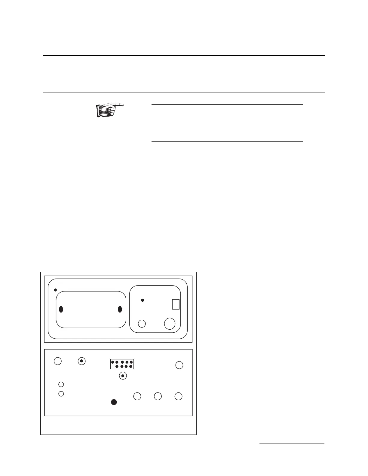
DI water
Resistivity level
max
min
fill
temp.
power on
CG604C
to CU
220
Vac
F1
F2
DI water
to laser
DI water
from laser
from tap
to drain
gnd
Front panel, CG604C
Rear panel, CG604C
CG604C front & rear panels.
from I/O panel
+24 V
temp set