Chapter V – Troubleshooting
5-13
C
996-0255 rev. b
5) On RB601 activate PGM -2, press on SHUTTER and Q-
SWITCH keys.
6) Press the FIRE button. The laser will now output a single
pulse.
7) Close the intracavity shutter by depressing the SHUTTER
button.
8) Remove the “burn” paper from the bag and examine the
pattern.
NOTE:
Remember the orientation of the paper when the “burn”
is taken. This will make it easier to determine which axis
of the mirror mount to adjust.
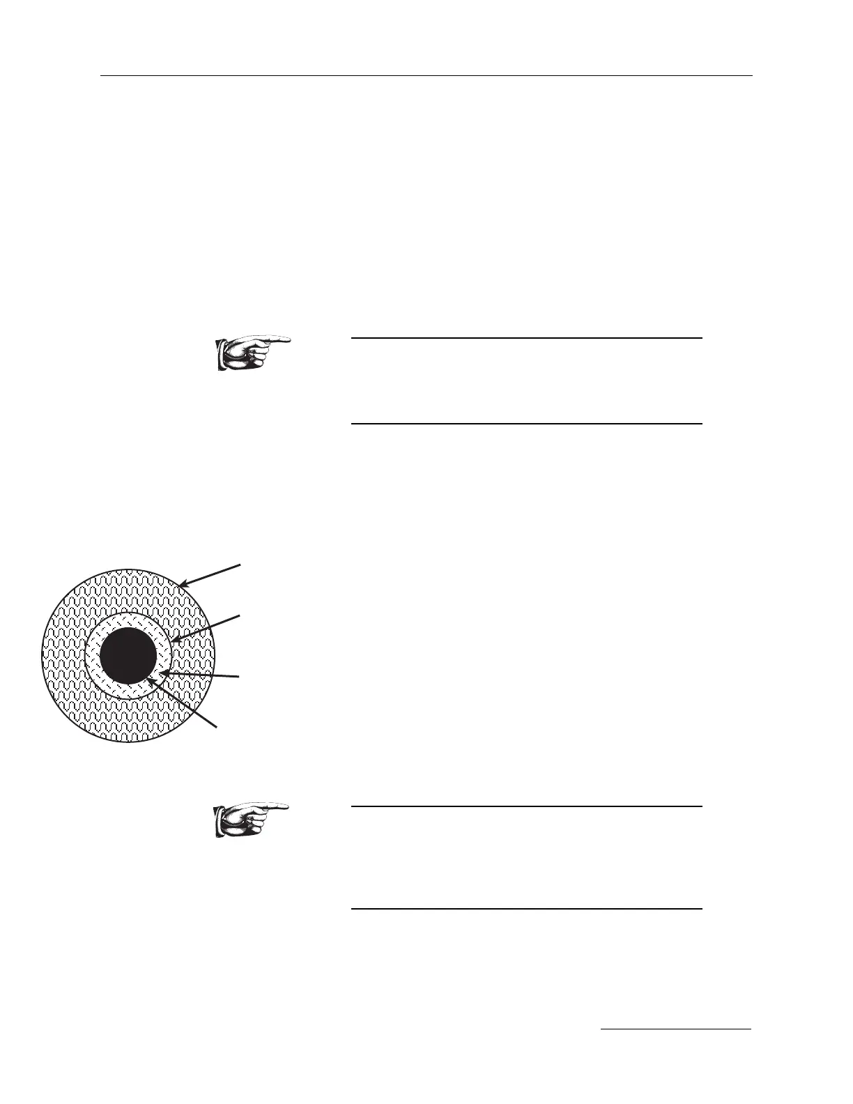
The burn pattern should be a dark circle roughly the same diameter as
the oscillator rod (see page 5-23). Inside of this circle there should be
another circle that is smaller and a light brown color. The light brown
indicates higher energy in that area.
9) Adjust the “rear” mirror (1) for optimum burn
pattern and maximum energy. Example: If the light
brown circle is in the lower half of the dark circle then
the beam needs to come up. This would require a vertical
adjustment.
Note: The mirror has both vertical and horizontal adjust-
ment. The vertical adjustment is the stainless steel
threaded post that is on the upper left corner of the
mount (when viewing the mount from the back). The
horizontal adjustment is on the lower right corner.
10) Repeat previous steps until the light brown circle is
centered.
NOTE:
If after following this procedure the output beam does
not look similar to the initial installation burn patterns
then a more complex realignment may be required.
Contact Continuum Service Department for information.
11) Check down stream alignment of optics, amplifiers and
crystals to insure that they are still correctly aligned.
12) Log service and date and resume normal operation.
Image as seen
through rod.
first
surface
of rod
second
surface
of rod
plastic
bag
burn pattern
on paper