Chapter III –Subassemblies
3-9
C
996-0255 rev. b
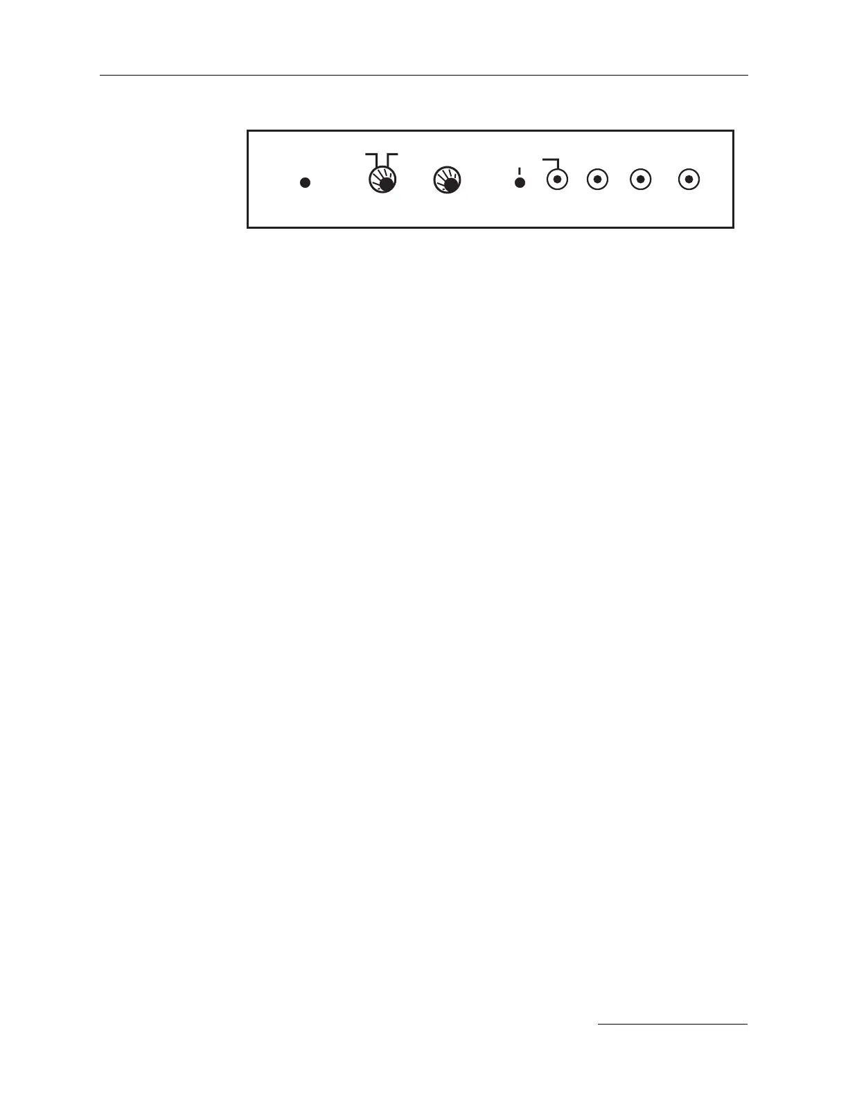
Seeder panel
on side of bench.
seeder
control
on
stby on
reset
freq piezo Qsw
offset volt
mnl
auto
dsbl
bid up time
signal is therefore present in INTERNAL and EXTERNAL
flashlamp trigger modes.
c) External Q-switch triggering via the Q-SWITCH
TRIGGER BNC connector —
Positive going TTL pulses trigger the Q-switch without
added delay when the INT/EXT switch is in the EXT
position, illuminating its red LED. NOTE: The VARI-
ABLE sync function is inoperative in the external Q-
switch trigger mode.
d) Fixed sync via the FIXED/TTL BNC connector —
The Q-switch trigger signal that drives the laser’s Marx
bank Pockels cell is buffered, level shifted, and delivered
to the BNC connector with minimum delay. It precedes
the firing of the Q-switch by approximately 35 ns.
e) The VARIABLE sync BNC connector is functional in
internal Q-switch trigger mode only. It allows a TTL signal
to appear either slightly before or slightly after the firing
of the Marx bank Pockels cell driver, with minimum jitter.
A screwdriver adjustment is provided to adjust the exact
timing desired.
f) Q-switch ramp up - when externally triggering a Preci-
sion II 9030 or 9050, the external Q-switch signal must
start at a delayed level (optimal Q-switch number + 200
µs), then this signal must change to the optimal Q-switch
level (~180 µs) at a rate of 10 µs/second. If this procedure
is not followed, then optical damage to the laser and
downstream optical components may/will occur.
3) Top view of laser bench
Electronics
When looking at the top of the laser bench, the dc motors for the har-
monic generators are visible and the Marx bank that drives the Q-switch
is shown below. The Marx bank schematic is on page 3-14.