Precision II Operation and Maintenance Manual C
5-26
996-0255 rev. b
11) Once the aperture alignment is correct, then the alignment
through the amplifier can be checked.
12) Position the burn paper (inside a plastic bag) approxi-
mately 4 inches from the output of the amplifier head.
13) On RB601 turn on SHUTTER and Q-SWITCH and then
press FIRE to get a single shot burn pattern.
14) On the RB601 turn off SHUTTER and Q-SWITCH.
15) Remove the burn paper from the plastic bag and carefully
examine the burn pattern (see page 5-24).
Note:
Once again the pattern will have two images. The
smaller lighter image should be centered on the larger
darker image.
16) Adjust the 7d mount. The screws located on the top of the
mounts control the vertical and horizontal axes. Adjust
this mount to align the oscillator beam through the ampli-
fier.
17) Make a small adjustment to the 7d mount and then repeat
the previous 4 steps until the alignment through the
amplifier is correct.
18) Once satisfied with the amplifier alignment, take burn
patterns after second and third harmonic crystals to verify
that the amplifier output passes cleanly through these
crystals.
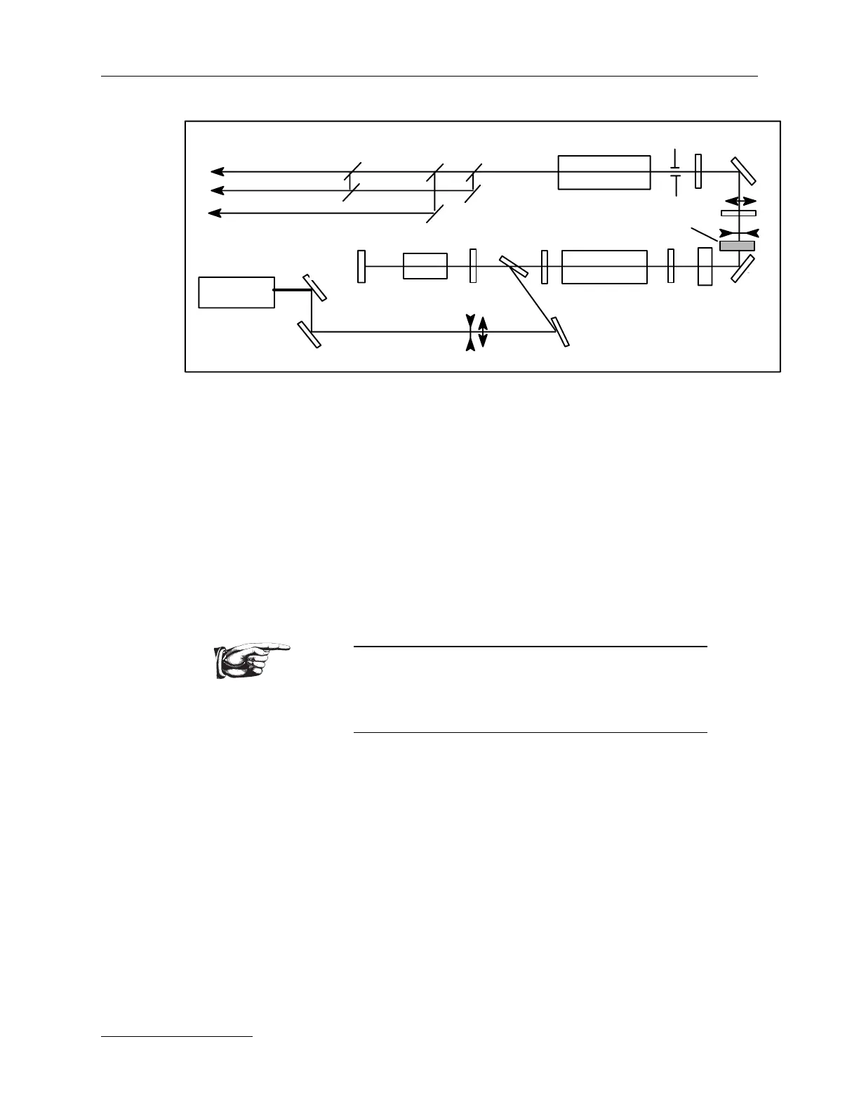
seeder
7c
7d
7a
7b
6
1
beam block position
1
seeder
7b
6
7a
7c
7d
beam block position