C
3-66
996-0255 rev. b
Precision II Operation and Maintenance Manual
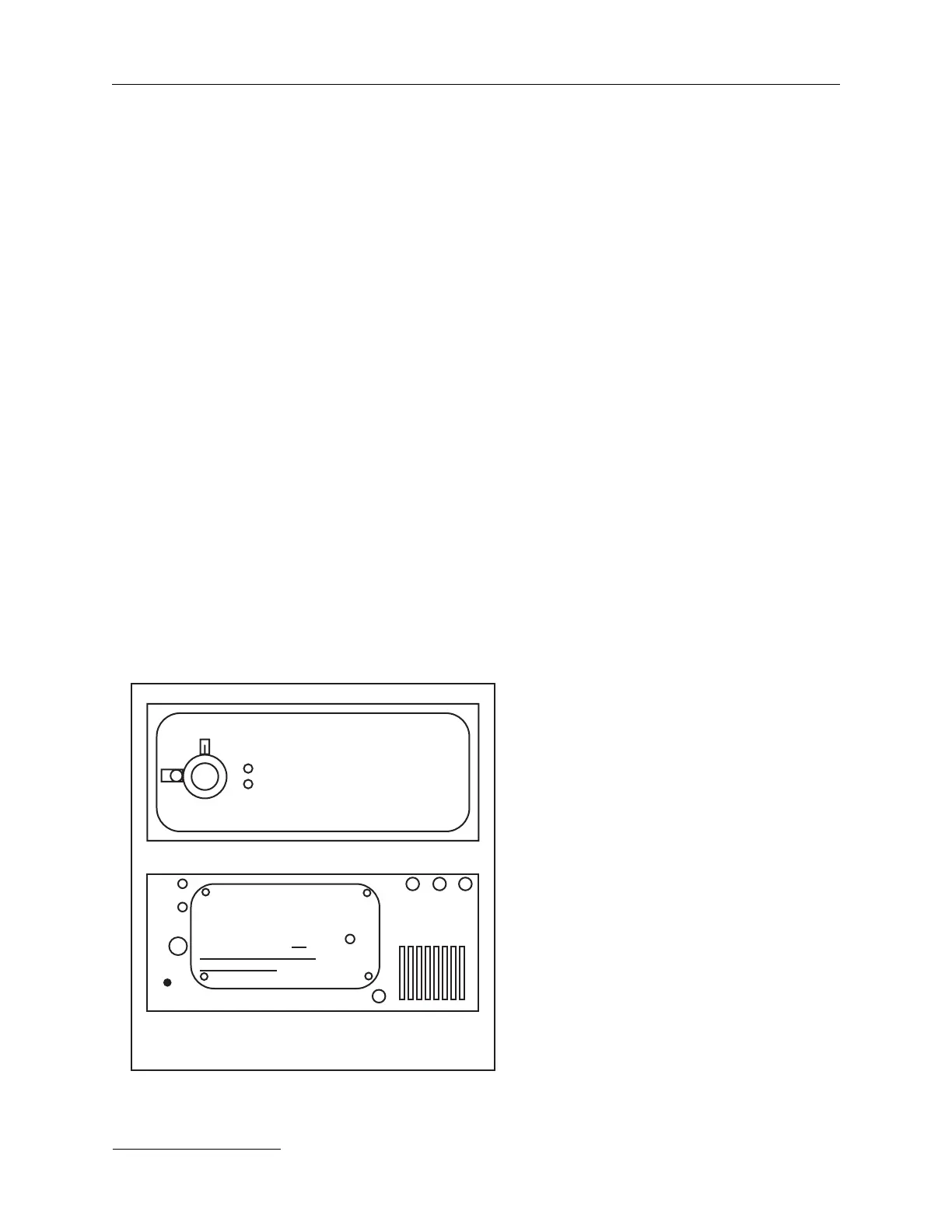
Front Panel
The front panel of the capacitor bank has two red indicator lights marked
POWER ON and SIMMER. There is also a DELAY ADJ dial.
Rear Panel
1) The HIGH VOLTAGE input J3, must be connected to the
power unit through the high voltage output.
2) J4 CU sync out has a variable trigger output which is
adjustable using the DELAY ADJ on the front panel. This
"CU sync out" is different than the "24 V/trig out" and
must not be used to trigger other capacitor banks.
3) "J5 +24V/trig" connects to the power unit for triggering. It
carries a synchronization signal which triggers the firing
of the laser head.
4) The 200-240 Vac input must be connected to the 3 pin MS
series connector marked “J1 input 220 Vac” on the far left
hand side of the rear panel.
5) The two fuse holders marked F1, F2 for the 200-240 Vac
input are 1.5 A slo fuses.
6) A grounding lug marked E1 Chassis gnd, on the lower
lefthand corner of the rear panel is
the electrical/chassis ground.
Grounding straps must be used to
connect this chassis to the corre-
sponding grounding lugs on the
control unit and the power units.
7) These panels of the C series
capacitor banks have a J6 BNC
plug. This J6 “simmer monitor
out” cable connects to the simmer
monitor plug on the power units.
Front panel, CB634C
Rear panel, CB634C
F1
+24V
/trig
in
CB 634C series
simmer
monitor
out
Chassis
gnd
E1
J1
input
220Vac
DELAY ADJ
POWER ON
SIMMER
CB634C
CB634C front & rear panels.
F2
WARNING
Disconnect all power &
discharge all capacitors
before connecting or
disconnecting J4.
Do
not operate without CB
unit connected.
HV INPUT MODULE
HIGH
VOLTAGE
input
J3
DO NOT REMOVE SCREWS
J6 J4 J5
CU
sync
out