30
The Piezo BNC provides a voltage ranging from -4 to +4 volts, proportional to 1/100th the
voltage applied to the piezo. The center of the piezo range is equivalent to 0 volts. Thus, -400, 0
and +400 volts on the piezoelectric element corresponds to -4, 0, and 4 volts, respectively, at the
Piezo BNC output.
This output can provide information concerning dither magnitude, rate of host laser frequency
drift, where the piezoelectric voltage is within its range, etc.
3.1.9 Build-Up Time BNC
This connector provides an output voltage ranging from 0 to 8 volts, proportional to the Q-
switch build-up time.
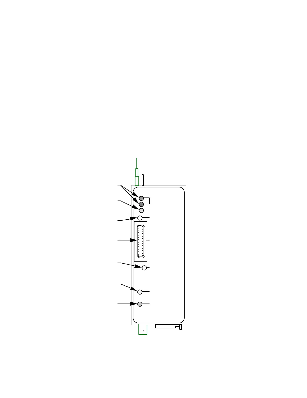
3.2 LASER HEAD CONTROL PANEL
In addition to the controls on the controller, several additional diagnostics and parameter
adjustments exist on the seeder’s laser head. A schematic of the top of the laser head is shown
below, and descriptions of the features follows.
LASER TEMP DRIVE
DIODE CURRENT
DITHER
ON - LASE
1 Hz-START/STANDBY
5 Hz-FAULT
D IAG NO STIC
LASER TEMP/FREQ
TRIG & PD
Top View
Diode Current LED
System Status LED
Laser Temperature LEDs
Dither Magnitude
Potentiometer
Diagnostic Connecto
Laser Frequency
Potentiometer
Trigger LED
Figure 3-2: Laser Head Top View
3.2.1 Laser Temperature LEDs