Chapter III – Subassemblies
3-45
C
996-0255 rev. b
Chapter III Subassemblies & Module Descriptions
mini index
Electronic cabinet wiring p. 3-16
PU620C front & rear panels p. 3-42
Block Diag., PU610C , PU620C p. 3-51
PU610C/620C PU Logic schem. p. 3-53 to 59
PU610C/630C wiring diagram p. 3-63
F. Power units, PU600C series
1. General description
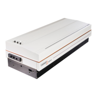
The PU600C series power units are Continuum's state of the art MOSFET
switching power supplies. These power units provide a current source to
charge the capacitor bank for all our high rep rate systems up to 60 Hz.
The PU610C is identical in construction to the PU620C except that the
PU620C has a second HV converter board, which yields a higher power
rating. The power rating for the PU610C is 1000 watts and the PU620C is
2000 watts. The PU630C units have a third converter board and a power
rating of 3000 watts. All the power units have been designed to operate
on international voltage levels so they are capable of running on 205-
255Vac 3 phase or 205-255 Vac single phase.
2. Structural Organization
The PU600C series each have two separate power supplies, the high
voltage supply and the 24 volt accessory supply.
a) High voltage supply
• Charge voltage can be adjusted from - 800 volts to -1900
volts from the front panel. The high voltage output uses J4
on rear panel.
• The power units have internal voltage limiting (factory
adjustable up to 2000 volts) in parallel with the front
panel voltage adjustment. In addition, an OVP circuit
stops the entire system in case of failure of the voltage
adjustment circuit.
b) The 24 volt accessory output is provided by an internally
mounted power supply mounted located next to the
power unit logic PCBA. A small standby circuit turns on
the 24 volt supply when a 2mA interlock signal (PU
enable) is received from the control unit. This signal uses
outputs J5 and J6 on the back panel. A µs +24 to 0 volt

 Loading...