Precision II Operation and Maintenance Manual
C
3-48
996-0255 rev. b
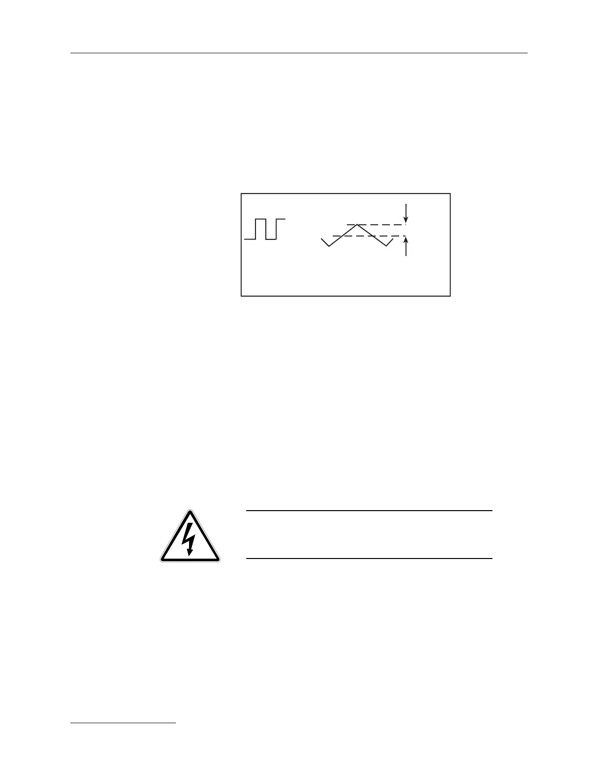
(when the ac line voltage is high), the frequency of the inverter increases.
This has the effect of lowering the current in L and thus the output
current of the power unit. An undervoltage cutoff is also provided in the
VCO PCBA to avoid laser operation in brown-out conditions.
The reactance-limited converter is controlled by the power unit logic
PCBA which receives optically-isolated commands from the logic unit.
Operation is initiated by the charge command and ended by an internal
sensing circuit (see HV sense schematic). A safety overvoltage cutoff is
provided protecting the capacitor banks from overvoltage. If the over-
voltage cutoff is activated, a red LED (labeled OVP on PU Logic board,
page 3-50) on printed circuit board is illuminated. The power unit logic
board will also issue a “fault” indication if:
a) a MOSFET thermostat opens, or
b) the power unit remains active for a period longer than
needed to charge the capacitor bank (this is to detect a
short circuit on the output, since the inverter normally
drives a “short circuit” each time it charges the capacitor
bank).
WARNING!! DANGEROUS VOLTAGE!!
LETHAL VOLTAGES MAY EXIST IN THIS SYSTEM AT
ANY TIME!
When the internal sense circuit detects the correct charge voltage, it
latches “off” the inverter and issues an optically isolated “end of charge”
signal to the logic unit. The logic unit then returns a “fire” signal to the
power unit.
When the fire signal is received, a pulse is issued to Q7 on the power unit
logic board, which briefly shorts the +24/trigger output to common. This
triggers an adjustable delay in the capacitor bank.
E (input)
Short circuit operation (zero volts output).
I
L
I pk (L)
0