Chapter III – Subassemblies
3-49
C
996-0255 rev. b
A number of protective circuits are provided to assure correct operation
of the power unit. There is the optically isolated “power unit enable”
input which turns on the +24V internal power supply and enables the
power units to operate. This permits complete control of the power unit
and capacitor bank from the logic unit. There is also an under voltage
cutoff circuitry on internal supply voltages to prevent abnormal opera-
tion of the inverter.
Part of the circuit is connected directly to the 205-255 volt power line.
Measurements should be made only with test instruments having a
differential input. Do NOT attempt to make single ended oscilloscope
measurements by “floating” the oscilloscope with an isolation trans-
former.
mini index
PU610C PCBA PU Logic p. 3-53 to 58
Schem. PU630 PU Power Board p. 3-59
PU630C Assy. p. 3-62
PU630C Wiring dia. p. 3-63
4. Connections and Signals
The power unit gets its power from the electronics cabinet's main ac bus
which has a 20A breaker. It receives its charge and fire commands from
the control unit which sets the clock frequencies and verifies system
securities.
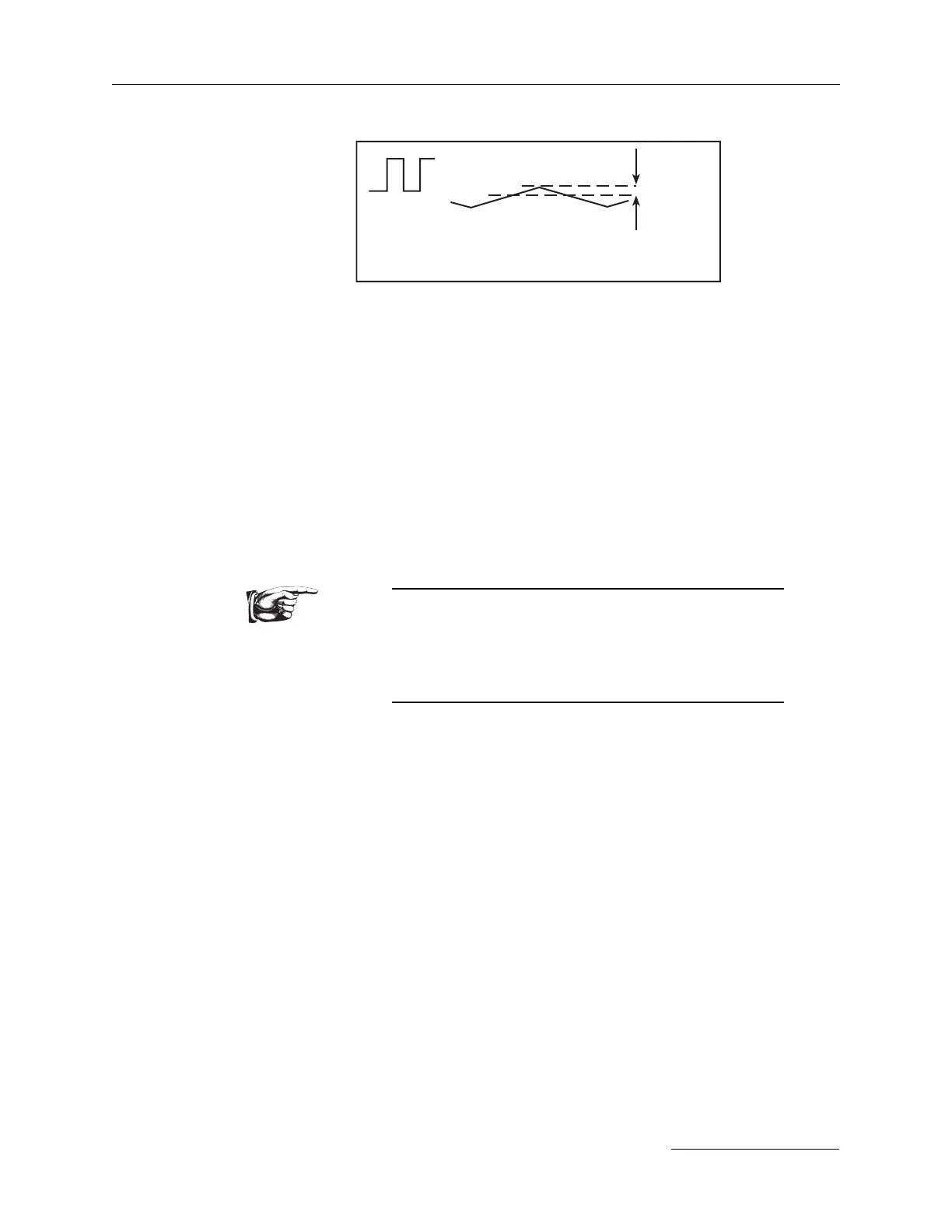
E (input)
Reduced I pk (L) as E (output) rises.
I
L
I pk (L)
0