Chapter V – Troubleshooting
5-19
C
996-0255 rev. b
7) Now press the SHUTTER button, located on the RB601, to
open the intracavity shutter.
8) Check the scope display for any change in the waveform.
When the shutter is opened, the flashlamp signal (on the
scope display) should increase slightly.
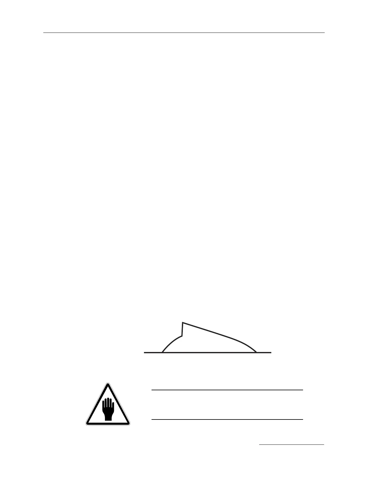
9) If the wave form starts with a gentle slope then abruptly
increases to a jagged peak, the laser is free-running.
10) If the laser is not free-running at this time, go to step 16.
To eliminate the free-running, adjustments to the polar-
ization optics need to be made.
11) At this time make a small adjustment to the vertical axis
of the Pockels cell through the vertical adjustment access
hole located at the top of the Pockels cell mount.
12) Note the vertical size of the scope display. If the trace
becomes smaller, then the adjustment was made in the
correct direction.
13) Continue to adjust the vertical axis until the amplitude of
the trace is as small as possible or until the free-running
stops.
If the free-running stops, then go on to step 15.
14) Now follow the same procedure as in steps 12 and 13 only
this time adjust the horizontal axis located on the lower
corner of the Pockels cell mount.
15) Continue these adjustments until the free-running has
been eliminated.
16) Close the intracavity shutter and increase the pump
voltage by 100 volts.
CAUTION:
Do not exceed 1.7kV unless otherwise instructed to do so by a
Continuum representative.
further adjustment required
flashlamp rise