Precision II Operation and Maintenance Manual C
3-28
996-0255 rev. b
remote box are restored. A low pitch beep will occur once
each cycle during this mode. The CU601C will also default
to LOCAL/MANUAL Mode.
c) Keyswitch
The keyswitch, when in the off position, performs a “cold
reset”, halts the main microprocessor board and disables
the four power unit interfaces on the rear panel. When the
keyswitch is turned on, the CU601C initializes, begins its
6 second countdown, defaults to the manual mode with
the shutter closed and is ready to accept commands.
d) Sync out
The sync out (BNC front panel) provides a 12V 5ns rise
time pulse variable in time from 175ns before lasing
output to 175ns after lasing. The time adjustment can be
made through a small hole to the left of the “SYNC OUT”
BNC on the front panel using a small flat blade screw-
driver or a pot “tweaker” tool.
e) YAG remote I/F
The YAG Remote I/F is a D9 female connector. This
connector is for the remote box plug.
f) RS232
The RS232 is a D25 female connector and is for RS232
control of the CU601C (see section on RS232, p. 2-13).
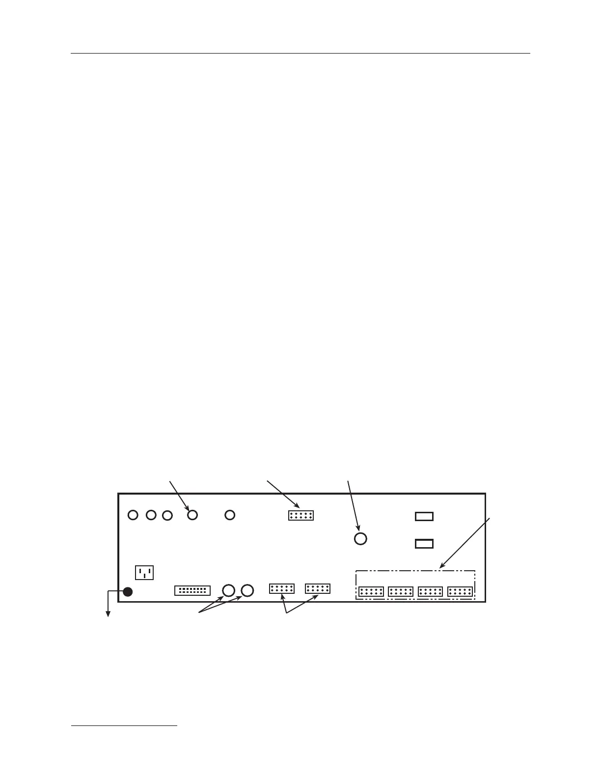
CU sync in
220Vac
J3
24V
laser
interlock
cooling
interlock
F1 F2
ext.
Q-sw in
HP/shtr
Q-sw.
A
B
crys. oven 1
crys. oven 2
J1
PU1 PU2 PU3 PU4
Accessory Driver
504-3204-2
ref. J7, p. 3-38
externals
PCBA EXT. ISO
504-9200-2
ref. J1, p. 3-35
PCBA EXT. ISO
504-9200-2
ref. J5, p. 3-35
PCBA
Controller
503-9900-2
sht. 7 of 9
ref. J5-8
p. 3-37
PCBA Controller
503-9900-2, ref. J3 & J4
sht. 6 of 9, p. 3-36
Accessory Driver
504-3204-2
ref. J6 & J5, p. 3-38
to ground
PCB references for rear panel connections.
F3