Menu 3
Parameter
structure
Keypad and
display
Parameter x.00
Parameter description
format
Advanced parameter
descriptions
Serial comms
protocol
Performance
48 Mentor MP Advanced User Guide
www.controltechniques.com Issue Number: 4
0: user setup
With the default value the user should enter the required speed controller gains.
1: Bandwidth setup
If bandwidth based setup is required the following parameters must be set correctly: Pr 3.20 = required bandwidth, Pr 3.21 = required damping factor,
Pr 3.18 = motor + load inertia (it is possible to measure the load inertia as part of the auto-tuning process, see Pr 5.12 on page 75), Pr 5.32 = motor
torque per amp.
Ki = J / (Kc x Kt) x (2π x Bandwidth / Kbw)
2
= Pr 3.18 / (rated drive current x Pr 5.32) x (2π x Pr 3.20 / Kbw)
2
Where: Kbw = √[ (2ξ
2
+ 1) +√((2ξ
2
+ 1)
2
+ 1) ]
Kp = 2 ξ √ [(Ki x J) / (Kc x Kt)] = 2 ξ √ [(Pr 3.11 {SP02, 0.62} x Pr 3.18) / (rated drive current x Pr 5.32)]
2: Kp gain times 16
If this parameter is set to 2 the Kp gain (from whichever source) is multiplied by 16. This is intended to boost the range of Kp for applications with very
high inertia. It should be noted that if high values of Kp are used it is likely that the speed controller output will need to be filtered (see Pr 4.12) or the
speed feedback will need to be filtered (see Pr 3.42). If the feedback is not filtered it is possible the output of the speed controller will be a square
wave that changes between the current limits causing the integral term saturation system to malfunction.
The motor and load inertia represents the total inertia driven by the motor. This is used to set the speed controller gains (see Pr 3.13) and to provide
torque feed-forward terms during acceleration when required (see Pr 4.11). It is possible to measure the inertia as part of the autotune process, see
Pr 5.12 {SE13, 0.34}.
The bandwidth is defined as the theoretical 3dB point on the closed-loop gain characteristic of the speed controller as a second order system. At this
point the phase shift is approximately 60°. This parameter is used to define the bandwidth used for setting up the speed loop gain parameters
automatically when Pr 3.17 = 1.
This is the damping factor related to the response of the system to a torque transient, and so if the damping factor is unity the response to a load
torque transient is critically damped. The step response of the speed controller gives approximately 10 % overshoot with unity damping factor.
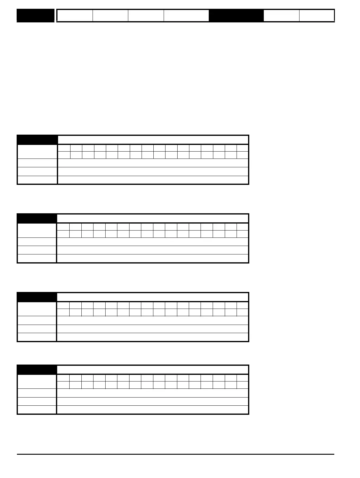
3.18 Motor and load inertia
Coding
Bit SP FI DE Txt VM DP ND RA NC NV PT US RW BU PS
5111
Range
0.00000 to 90.00000 kg m
2
Default 0.00000
Update rate Background (1s) read
3.20
Bandwidth
Coding
Bit SP FI DE Txt VM DP ND RA NC NV PT US RW BU PS
111
Range 0 to 50 Hz
Default 1 Hz
Update rate Background (1s) read
3.21
Damping factor
Coding
Bit SP FI DE Txt VM DP ND RA NC NV PT US RW BU PS
1 111
Range 0.0 to 10.0
Default 1.0
Update rate Background (1s) read
3.22
Hard speed reference
Coding
Bit SP FI DE Txt VM DP ND RA NC NV PT US RW BU PS
11 11
Range ±MAX_SPEED_REF rpm
Default 0.0
Update rate 4 ms read