Manuale di Istruzioni
Instruction Manual
Rev.1 EN 23/08/2018
103
If the system linearity is not acceptable within the field 10% to 100% full scale, we
recommend the following values, 10%, 20%, 60%, 100%. Particular operator
experience or needs may lead be the use of other values.
Proceed as here after described to operate the compression machine and achieve the
different load steps;
3. Correctly place the reference instrument (e.g. load cell) between the compression
platens of the test frame;
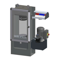
4. When ready, turn ON the pump motor by acting on the relevant switch (note that the
pump motor switch is self-retaining when the mains electricity supply is connected);
in the meantime, set lever A up and lever B back on the flow control valve (rapid
approach phase); and the ram of the test machine will start to rise;
Fig. 5-21
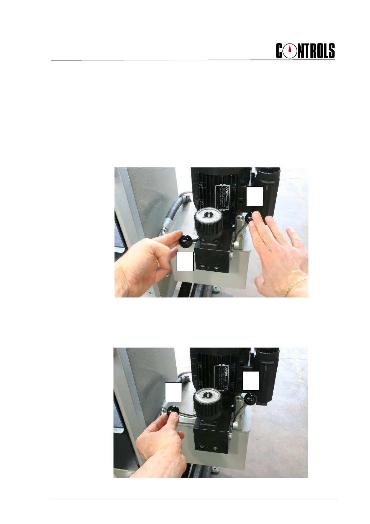
5. When the load cell is close to the upper platen of the compression machine it is
recommended that the load rate is decreased so as to not apply a shock load to the
cell. To do this set lever A up, turn lever B slowly forward to control the speed of the
piston with the flow control valve;
Fig. 5-22