Manuale di Istruzioni
Instruction Manual
Rev.1 EN 23/08/2018
61
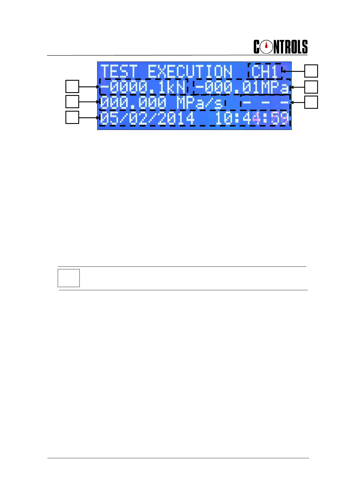
Fig. 4-8
This screen shows:
A. The channel number selected for the test
B. The actual load value measured by the load sensor connected to the WIZARD 2
C. The strength (resistance) of the sample
D. The test speed
E. The trend indicator of actual load rate with respect to the theoretical set load rate
F. Date and time.
At this point, the WIZARD 2 is ready to carry out the test on the sample as follows.
The load rate is controlled using the special valve with dial gauge handle mounted on the
pump. The correct load rate can be set by following the load rate indicator on the
WIZARD 2 and rotating the load rate valve either clockwise or counter clockwise.
NOTE:
By rotating the valve clockwise, the load rate is decreased, by rotating counter-clockwise
the rate is increased.
A
C
E
B
D
F