10/2007 - Art. Nr. 13 017 700B10
Start-up
Description and settings
Combustion air
1-stage burner
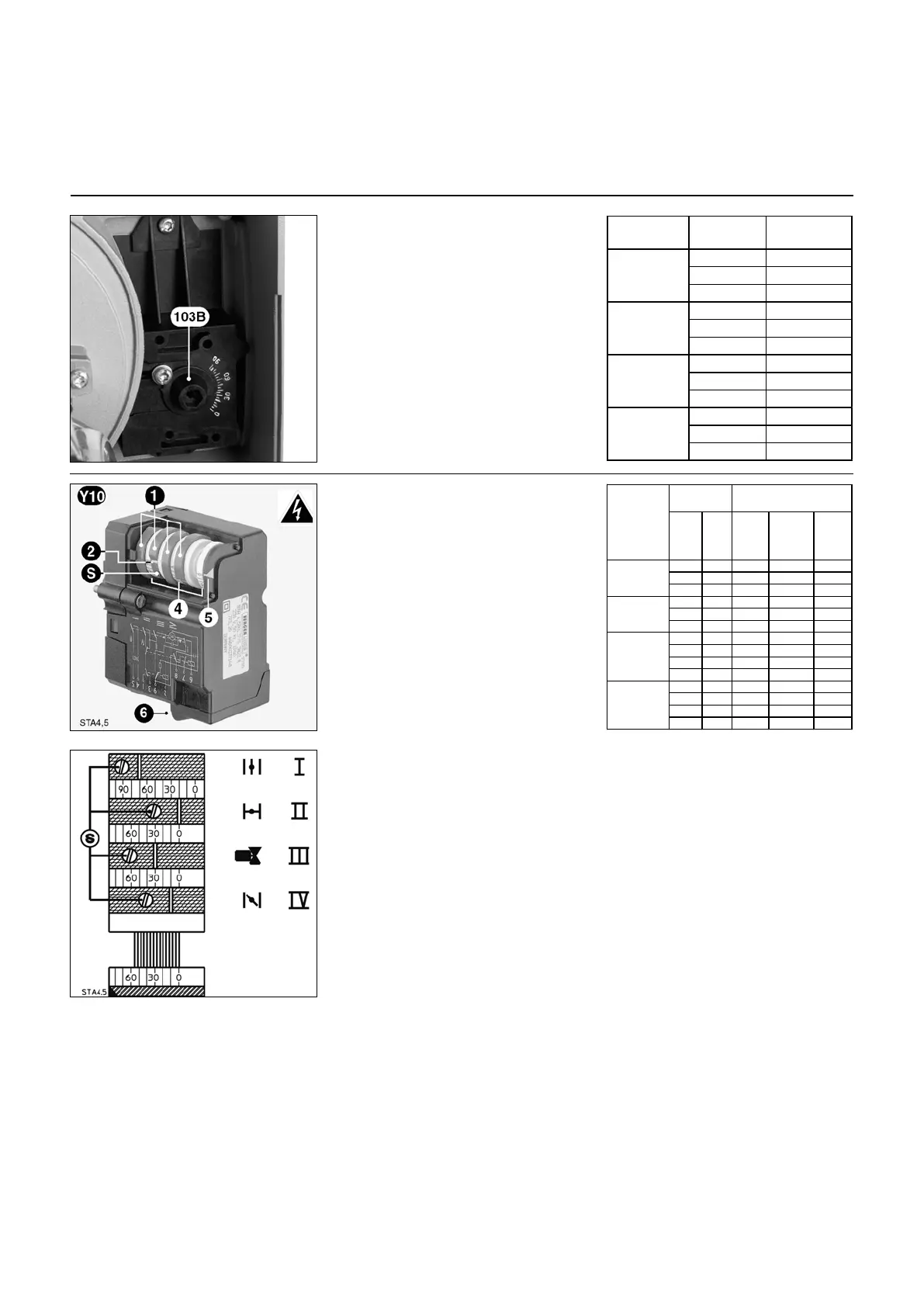
Manual control 103B
• Loosen the locking screw.
• Select the opening of the air flap
between 0 and 9 from the table as a
function of the power to be delivered.
• Adjust at the indicated value.
• Tighten the screw.
2-stage burner
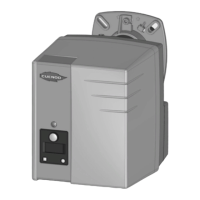
Servomotor Y10
1 Four red adjustable cams
2 Positioning mark for the cams
relative to the graduated
cylinders 4
S Cam adjusting screw
4 Three cylinders graduated
from 0 to 160°
5 Air flap positioning pointer
6 Plug-in electrical connector
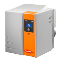
Cam functions
Cam Function
I Nominal air flow
II Air closing on shutdown: 0°
III Stage 2 fuel valve energized
• Set between value of the cam IV
and value of the cam I. In most
cases, a setting just at the half is
suitable.
IV First stage air flow.
Setting
• Remove the cover.
• Check zeroing of cam drum.
• Pre-set the cams according to the
boiler power and the values shown in
the accompanying table.
To do so:
• Actuate the cams using screws S.
The angle position is read in relation to
the index placed on each cam.