10/2007 - Art. Nr. 13 017 700B14
Start-up
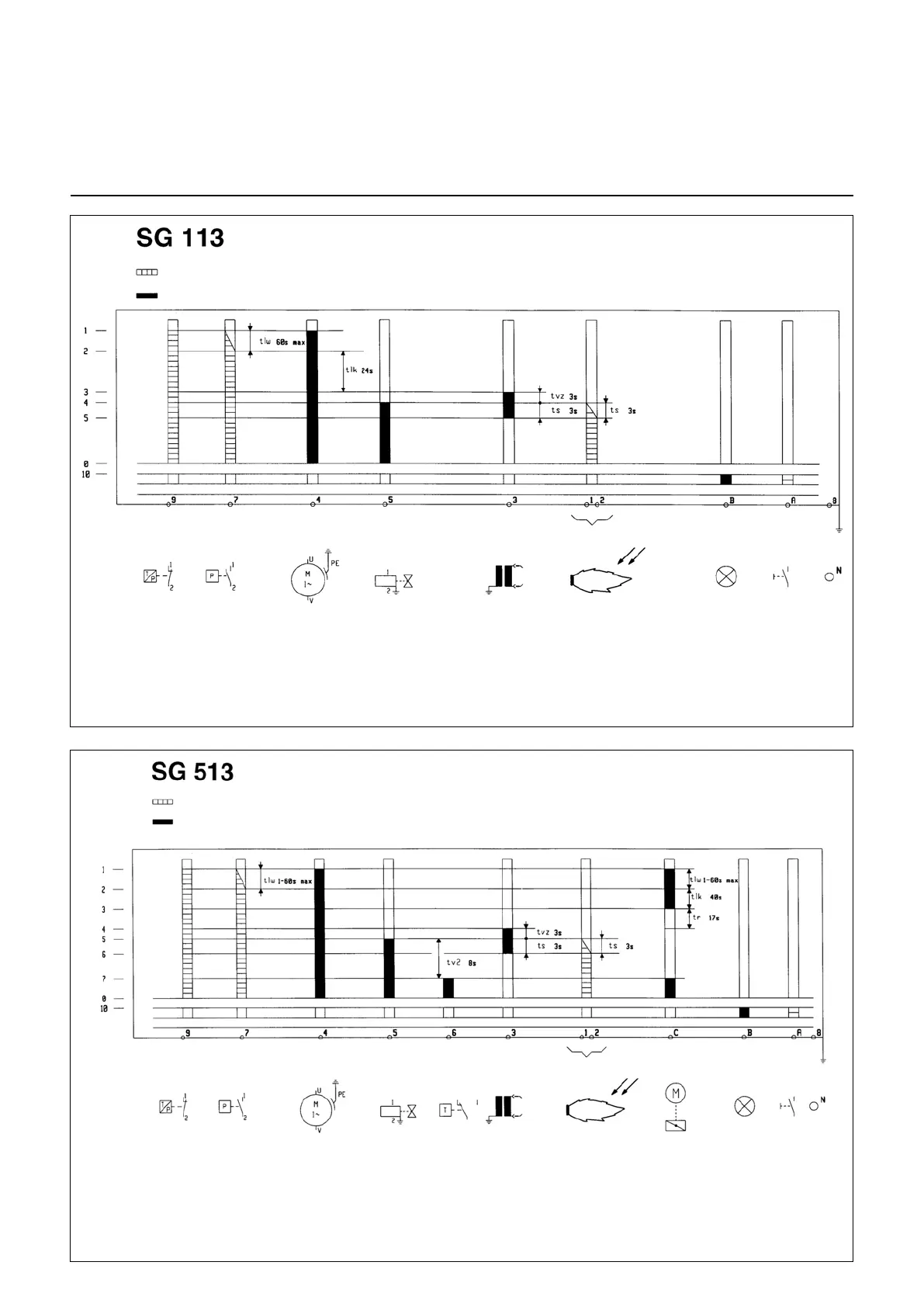
Unit operation diagrams
Input signals required
Output signals
Limiter Air pressure switch Burner motor Fuel valve Transformer Flame control Defect Unlocking
1 Unit and motor start-up
2 Air checking
3 End of preventilation and
transformer firing
4 Fuel valve energising
5 Flame and operating
conditions checking
0 Control end
10 Defect mode
tlw Air pressure switch holding time
tlk Preventilation time
tvz Pre-firing time
ts Safety time
Limiter Air pressure switch Burner motor Gas valve Regulator Ignition transformer Flame Servomotor Trouble Reset
1 Powering up unit, motor and S.M.
2 Checking if air is present
3 End of preventilation
4 Powering up ignition transformer and end
of preventilation
5 Powering up gas valve
6 Checking if flame is present
7 Powering up S.M. and gas valve; operation state
0 Regulator stop
10 Trouble mode
tlw Air pressure switch standby time
tlk Damper motor opening time and preventilation
count down
tr Damper motor closing time
tvz Preignition time
ts Safety time
tv2 Minimum time between gas valve 1 and 2
Required input signals
Output signals