10/2007 - Art. Nr. 13 017 700B 19
Maintenance
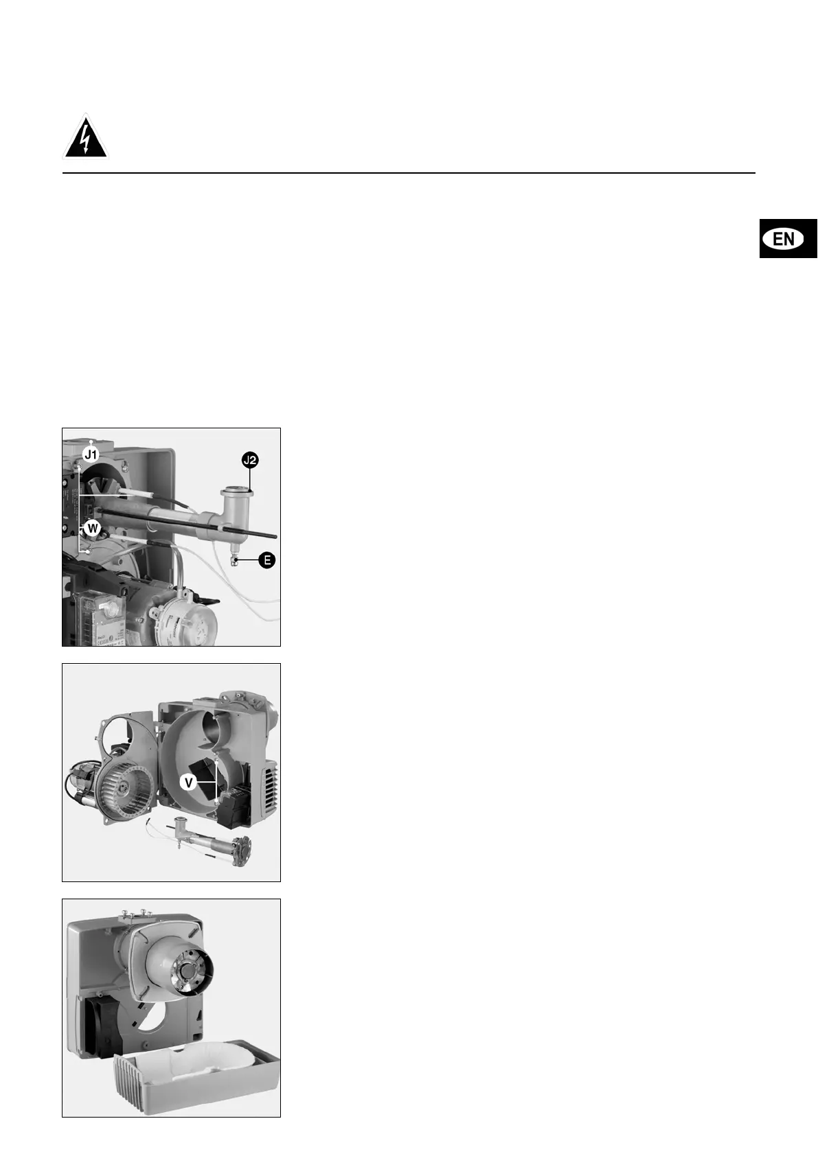
Checking combustion components
• Disconnect the ignition cable on the
transformer.
• Disconnect the ionisation sensor cable
on the cover.
• Remove the three screws W from the
cover.
• Fully release the lock nut of the gas
line by turning in a clockwise direction.
• Completely loosen spherical-head
screw E by turning in an anti-
clockwise direction.
• Remove the combustion head.
• Check the condition and the settings:
of the ignition electrode, the ionisation
probe, the turbulator and the diffuser.
• Change any defective parts.
• If necessary, remove any dust from the
parts that are accessible from the cover.
• When re-assembling, check for the
presence and the correct positioning
of the O-ring type sealing ring J2.
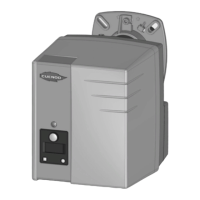
Cleaning the air box
• Remove the two screws from the gas
manifold on the cover.
• Disengage the burner (bayonet) and
put it on the ground.
• Remove the two screws V from the
air box.
• Clean the air box and the acoustic
insulation foam.
• Remount the air box and the burner.
• Secure the gas manifold:
Check the presence and the
position of O-ring
J1
in the flange
on the housing.
• Check the tightness.
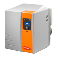
Cleaning the aeraulic circuit
• Remove combustion components.
• Disconnect motor.
• Remove all five motor plate screws,
starting from the bottom.
• Hook the plate on the cover.
• Clean the aeraulic circuit and the
turbine.
• Reassemble.
Important
The burner should be serviced at least
once a year by a trained specialist.
• Turn off power supply at isolator
switch.
• Check absence of voltage.
• Close gas input.
• Check for leaks:
Do not use pressurized liquids or
chlorinated products.
The setting values are indicated in the
paragraph:
“Start-up”
.
Use only original spare parts.
• Remove the burner cover.
Disassembling the connecting
nozzle.
• Disconnect flange 7P.
• Remove the two screws from the gas
ramp on the housing.
• Unscrew the bracket screw.
• Remove the burner and place it on the
ground.
• Loosen the four screws for the
connecting nozzle by five turns and
remove the connecting nozzle.
• Replace, index and secure the
connecting nozzle.
• Reassemble all parts in the reverse
sequence to disassembly.
• If required, fill space between the quarl
and the new blast tube with refractory
material.
• Check for leaks later.
Checking gas filter
The external or valve filter must be
examined at least once a year and filter
element changed if filthy.
• Remove cover screws.
• Remove filter element. Make sure no
dirt is left in its housing.
• Install a new, similar element.
• Replace seal, cover and screws.
• Open quarter-turn fuel hand-operated
valve.
• Check airtightness.
• Check combustion.
Gas valves
These valves do not require any special
maintenance.
No repairs may be carried out on them.
Faulty valves must be replaced by a
technician, who will then recheck air/
water tightness, performance and
combustion.
Checking connections
On electrical plate, fan motor and
servomotor.
Cleaning cover
• Clean cover with a water and
detergent mixture.
• Place cover back on.
Note
After each maintenance operation:
• Check gas combustion under actual
working conditions (doors closed,
cover in place, etc.) and check all
circuits for possible leaks.
• Perform safety checks.
• Record results in the relevant
documents.