10/2007 - Art. Nr. 13 017 700B12
Start-up
Description and settings
2-stage gas valve
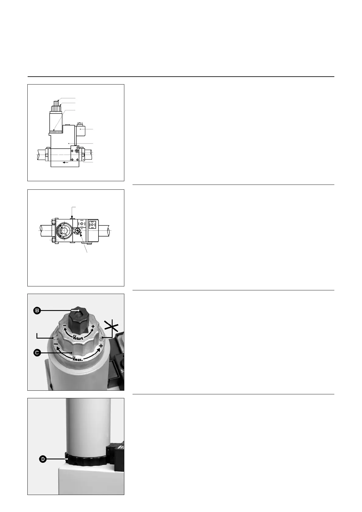
2-stage gas valve
MB ZRDLE...B01S..
Compact assembly consisting of a filter,
an adjustable air pressure switch, a non
adjustable, quick acting safety valve, an
adjustable pressure controller, two
valves 1
st
and 2
d
stage of which the flow
stage is incrementally adjustable on
opening.
Upon delivery:
- The valve is preset for the power
values shown in the table
- The progressive rate is set to a
two-turn opening
- The stage two valve is open to its
maximum extent.
- The pressure switch is set to minimum.
General setting procedure
The setting for stage two is only carried
out by actuating the pressure controller:
the stage two valve (button C) is open to
its maximum extent.
The progressive rate upon ignition and
changing from one stage to another is
set by actuating button B.
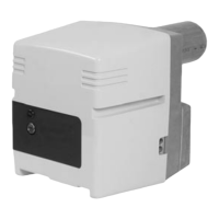
The setting for stage one is carried out
by actuating crown D.
Controller setting:
Controller pressure measurements are
carried out at pBr.
The pressure setting provides the
desired flow rate.
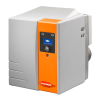
Setting the progressive rate:
This hydraulic brake function acts on the
ignition flow rate and the shift between
stages.
• Unscrew plastic stopper B.
• Turn it around and use it as a spanner.
The setting has a 3-turn stroke.
• Rotate it in the direction of the:
- arrow: the progressive rate will
increase
+ arrow: the progressive rate will
decrease.
Particular case
Nominal flow stage setting
This is necessary only if the flow stage
read under a pressure of 4 mbar on the
controller is too high.
Do as follows:
• loosen the locking screw avoiding to
touch the opposite painted screw.
Plug C has a 4.5-turn travel length.
• Make the screw rotate in a cw direction
arrow -. The flow stage decreases
and vice versa.
It might be necessary to adjust the
pressure.
• Tighten the locking screw.
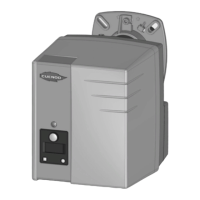
Incremental advance setting
Main flow stage
setting
Setting 1
st
stage
Pressure switch
Coil
Access to filter
Connecting
flange
pBr
Pressure
controller
setting
S 20 = 4 to 20 mbar
S 50 = 4 to 50 mbar
Locking
screw
Painted
screw
Setting the stage one flow rate
• Unscrew the locking screw without
touching the painted screw opposite.
• Rotate crown D clockwise by hand
(without using a tool): the flow rate will
decrease and vice versa.
• Tighten the locking screw back up.