10/2007 - Art. Nr. 13 017 700B 5
Installation
Assembly
4
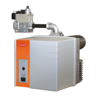
Burner
The burner is secured on the boiler with
the flange supplied. The drilling
recommended for Ø b is written in
boldfaced figures on the drawing. If Ø a
on the boiler exceeds the maximum Ø
on the drawing (see technical data),
provision should be made for a cover
plate in front.
• Mount the flange and its gasket on the
boiler.
• Check the tightness.
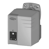
The burner is installed in position 1.
If necessary, it may be installed in
position 2.
• Insert the burner head into the flange
(penetration: see boiler manual).
• Tighten the bracket by raising the
burner slightly.
• If assembly in position 2, unclip the
brand plate, rotate it by 180° and clip it
back onto the hood.
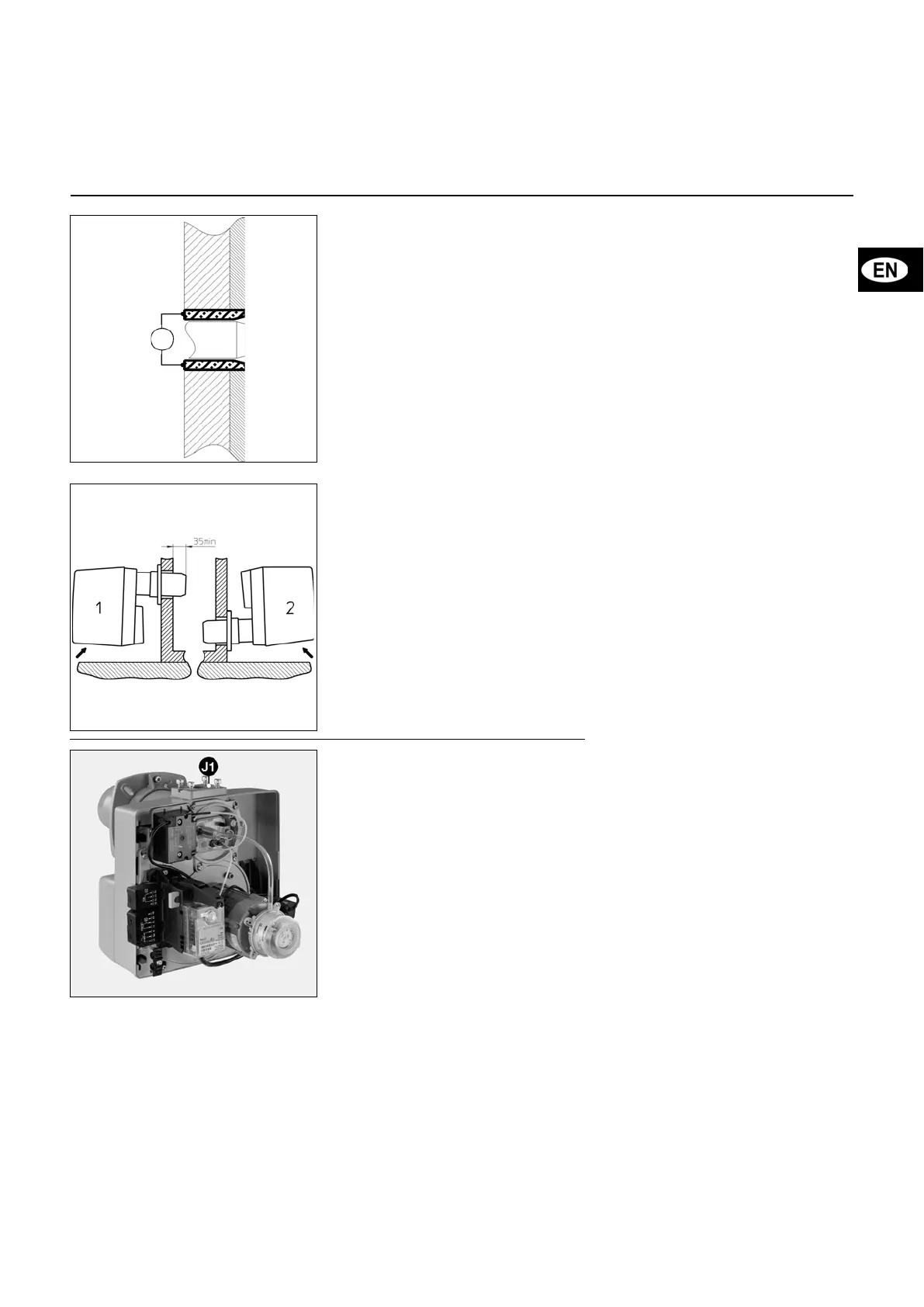
When the generator incorporates a door
for access to the furnace, pack the
space 4 between the quarl and the blast
tube with a refractory material (not
supplied).
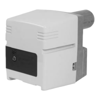
Gas manifold
• Check presence and position of O-ring
J1 in manifold flange.
• When fitting gas manifold, valve coils
must be in the vertical top position.