10/2007 - Art. Nr. 13 017 700B8
Start-up
Checking and setting
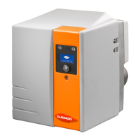
Combustion head, secondary air
NC16/NC21
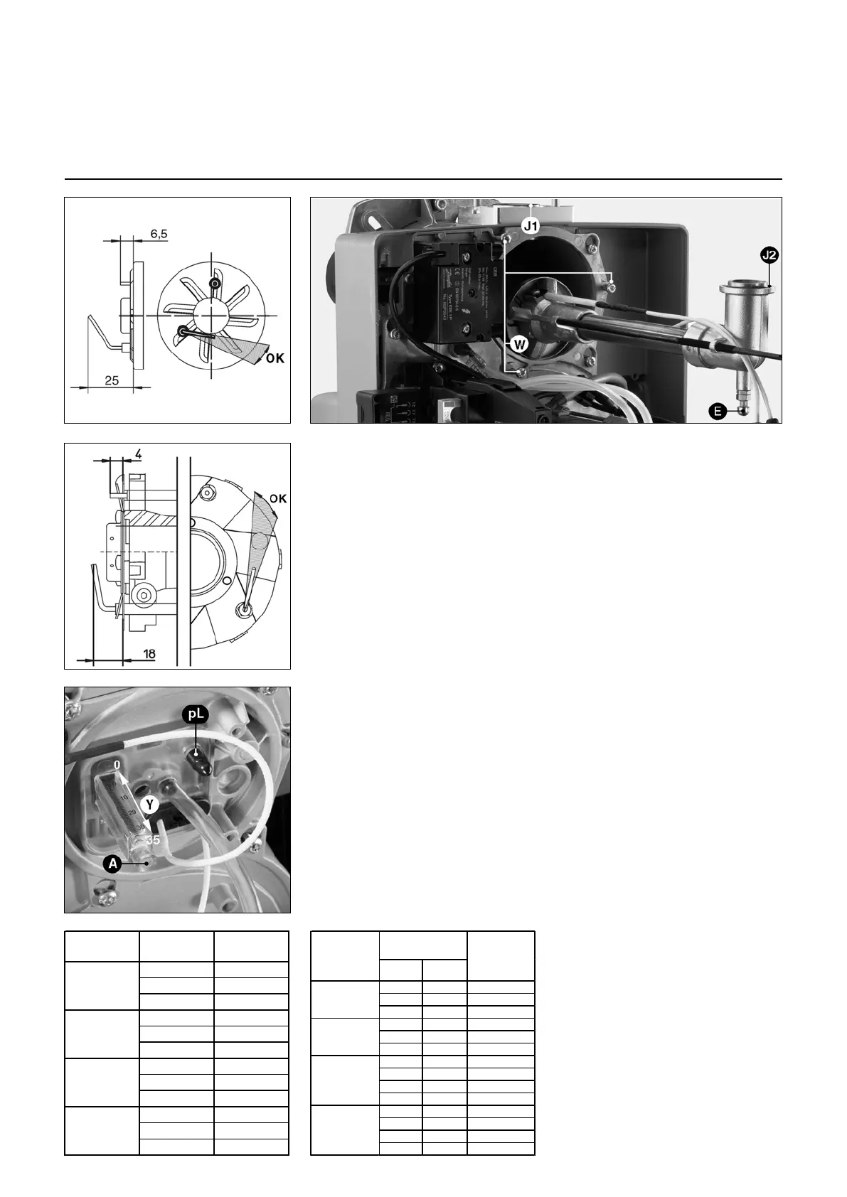
NC12
Checking and setting combustion
head
Burner is supplied already set for natural
gas.
• Check positions of ignition electrode
and ionisation sensor as per the
drawings enclosed.
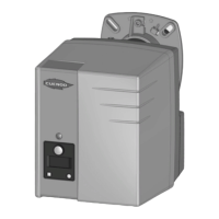
• During assembly, check that O-ring J2
is fitted and correctly positioned.
• Unscrew spherical-head screw E
(clockwise) to secure the head.
• Fit the grommet onto the cover.
• Fasten the cover (3 screws W).
• Tighten the ignition cable and connect
it to the transformer.
• On the cover, connect the connection
box’s integral ionisation cable.
• Check the assembly is airtight.
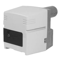
Secondary air
This is the amount of air flowing between
the turbulator diameter and blast tube.
Turbulator position (dimension Y) is read
on a template 0 to 35mm scale.
Maximum secondary air is set at 35 and
minimum at 0.
According to the following:
- requested power output
- firing quality (shock, vibration, judder,
time lag),
- combustion quality,
this value can be changed.
Setting
This is performed without removing
burner, whether stopped or in operation,
according to enclosed values.
By reducing dimension Y (in a cw
direction), CO
2
increases and vice
versa.
• Turn screw A in the direction desired.
1-stage
burners
Burner