CVC TECHNOLOGIES, INC. CVC 400 OPERATION MANUAL 2011.3.10
i
CONTENTS
1. ABOUT THIS MANUAL
1.1 About This Manual .............................................................................................. 1-1
1.2 Additional Information.......................................................................................... 1-1
2. SPECIFICATIONS
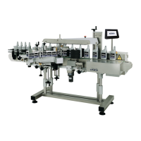
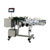
2.1 Machine Specifications........................................................................................ 2-1
2.2 Label Specifications ............................................................................................ 2-2
2.3 Hot Stamp Printer Specifications (Optional).......................................................... 2-5
3. SAFETY REGULATIONS
3.1 General Safety Rules ........................................................................................... 3-1
3.2 Warning Signs..................................................................................................... 3-1
3.3 Warning Sign Placements.................................................................................... 3-2
3.4 Important Safety Notices ................................................................................... 3-3
4. INSTALLATION
4.1 Standard Area Conditions .................................................................................... 4-1
4.2 Minimum Machine Operation Space..................................................................... 4-1
4.3 Transportation Precautions .................................................................................. 4-2
4.4 Transportation Procedures................................................................................... 4-2
4.5 Positioning and Adjustment of Machine Level and Height ..................................... 4-4
5. INSTALLATION PROCEDURES
5.1 Power Connection ............................................................................................... 5-1
5.2 Compressed Air Connection (Optional) ................................................................ 5-1
5.3 U-Type Spring Clip Mounting (Optional)................................................................ 5-2
5.4 C60 Printing Type Arrangement (Optional)............................................................ 5-3
6. MACHINE GENERAL LAYOUT
6.1 Parts Identifications............................................................................................. 6-1
6.2 Machine Parts Functions ..................................................................................... 6-5
6.3 Machine Control Parts Functions ......................................................................... 6-6
6.4 Pneumatic Control System (Optional)................................................................... 6-7
6.5 General Layout and Dimensions........................................................................... 6-8
7. POWER BOX
7.1 Locations of Printed Circuit Board (A) .................................................................. 7-2
7.2 Printed Circuit Board............................................................................................ 7-4
8. HHT DISPLAY INSTRUCTIONS
8.1 Control Panel Descriptions................................................................................... 8-1
8.2 LCD Display Descriptions .................................................................................. 8-4
8.3 AUTO ADJ Display Sequence............................................................................... 8-6