Step Action
8 Turn the adjusting knob clockwise onto the top of the adapter until the holes
i
n the inner adjusting tube are level with the holes in the outer adapter tube.
(See Chapter 3 Column descriptions, on page 18 for respective size of the
adjusting knob.)
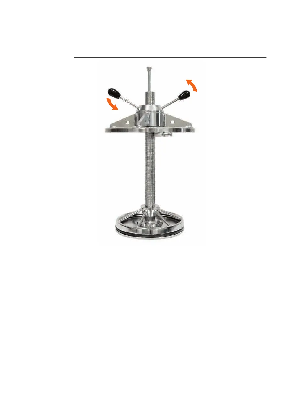
9 Use a flashlight and a screwdriver through one hole to lock the inner tube in
position. Then two of the adapter head screws can fasten the sealing unit in
place.
6 Maintenance
6
.5 Disassemble and assemble the adapter
BPG Columns Operating Instructions 29193223 AB 109
 Loading...