xStack® DES-3200 Series Layer 2 Managed Fast Ethernet Switch
161
Select IGMP to instruct the Switch to examine the Internet Group Management
Protocol (IGMP) field in each frame's header.
Type – Enter the IGMP packet type value.
Select TCP to use the TCP port number contained in an incoming packet as the
forwarding criterion. Selecting TCP requires that you specify a source port mask
and/or a destination port mask.
TCP Source Port - Specify a TCP port number for the source port form (0-65535).
TCP Destination Port - Specify a TCP port number for the destination port form (0-
65535).
Flag Bits - The user may also identify which flag bits to filter. Flag bits are parts of a
packet that determine what to do with the packet. The user may filter packets by
filtering certain flag bits within the packets, by checking the boxes corresponding to
the flag bits of the TCP field. The user may choose between urg (urgent), ack
(acknowledgement), psh (push), rst (reset), syn (synchronize), fin (finish).
Select UDP to use the UDP port number contained in an incoming packet as the
forwarding criterion. Selecting UDP requires that you specify a source port mask
and/or a destination port mask.
UDP Source port - Specify a UDP port number for the source port form (0-65535).
UDP Destination port - Specify a UDP port number for the destination port form (0-
65535).
Select Protocol ID - Enter a value defining the protocol ID in the packet header to
mask.
Protocol ID - Specify that the rule applies to the IP protocol ID traffic from (0-255).
User - Specify the Layer 4 part value.
Action Select Permit to specify that the packets that match the access profile are forwarded
by the Switch, according to any additional rule added (see below).
Select Deny to specify that the packets that match the access profile are not
forwarded by the Switch and will be filtered.
Allows the entry of a name for a previously configured VLAN.
Time Range Name
Tick the check box and enter the name of the Time Range settings that has been
previously configured in the Time Range Settings window. This will set specific
times when this access rule will be implemented on the Switch.
Ticking the All Ports check box will denote all ports on the Switch.
Click the Apply button to accept the changes made.
Click the <<Back button to discard the changes made and return to the previous page.
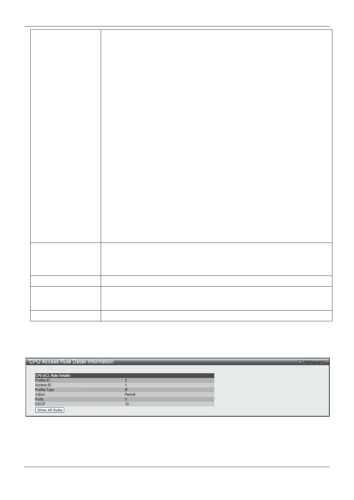
After clicking the Show Details button in the CPU Access Rule List, the following page will appear:
Figure 7-33 CPU Access Rule Detail Information (IPv4 ACL)
Click the Show All Rules button to navigate back to the CPU Access Rule List.
 Loading...