xStack® DES-3200 Series Layer 2 Managed Fast Ethernet Switch
38
• Property – To pop up a window to display the group information.
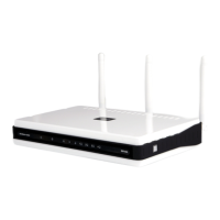
Member Switch Icon
Figure 3-22 Right-clicking a Member icon
The following options may appear for the user to configure:
• Collapse – To collapse the group that will be represented by a single icon.
• Expand – To expand the SIM group, in detail.
• Remove from group – Remove a member from a group.
• Configure – Launch the web management to configure the Switch.
• Property – To pop up a window to display the device information.
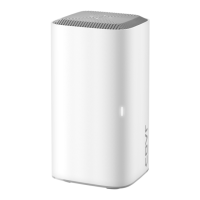
Candidate Switch Icon
Figure 3-23 Right-clicking a Candidate icon
The following options may appear for the user to configure:
• Collapse – To collapse the group that will be represented by a single icon.
• Expand – To expand the SIM group, in detail.
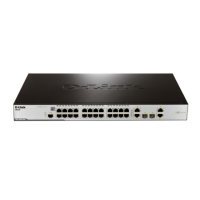
• Add to group – Add a candidate to a group. Clicking this option will reveal the following dialog box for
the user to enter a password for authentication from the Candidate Switch before being added to the
SIM group. Click OK to enter the password or Cancel to exit the dialog box.
Figure 3-24 Input password window
• Property – To pop up a window to display the device information.
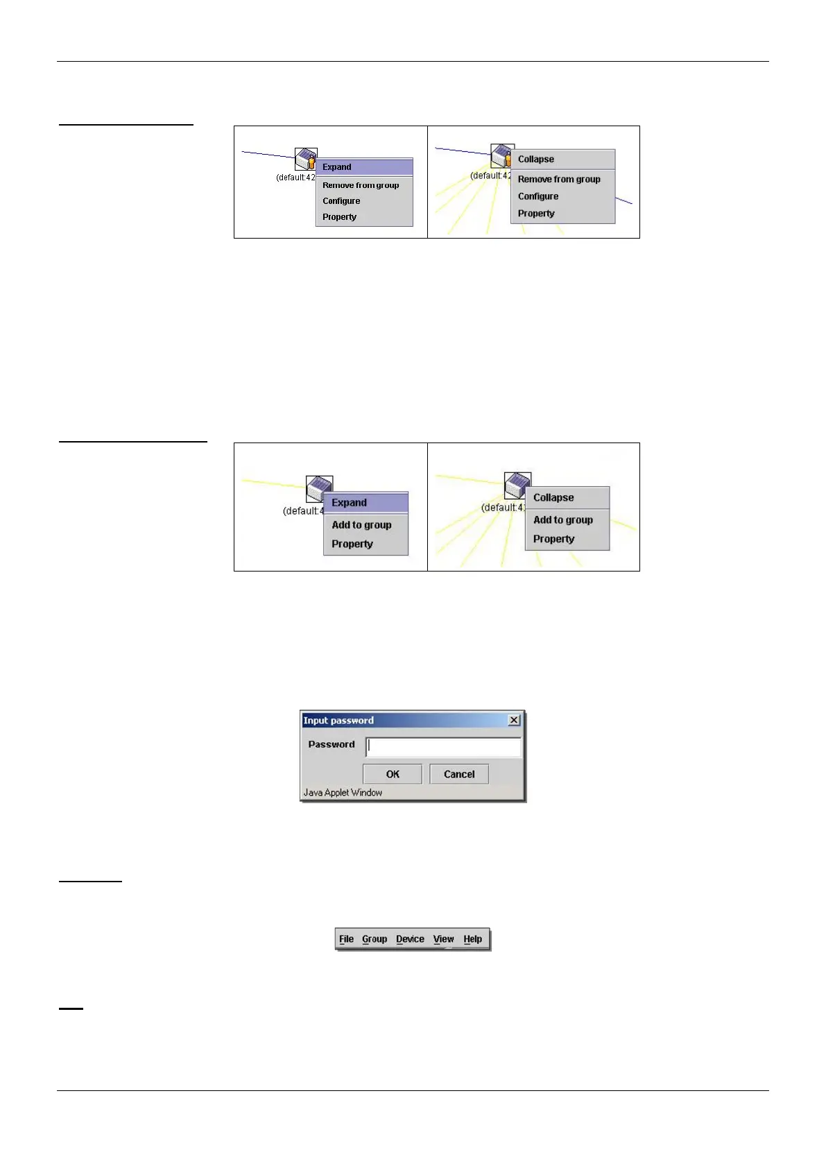
Menu Bar
The Single IP Management window contains a menu bar for device configurations, as seen below.
Figure 3-25 Menu Bar of the Topology View
File
• Print Setup – Will view the image to be printed.
• Print Topology – Will print the topology map.
• Preference – Will set display properties, such as polling interval, and the views to open at SIM startup.
 Loading...